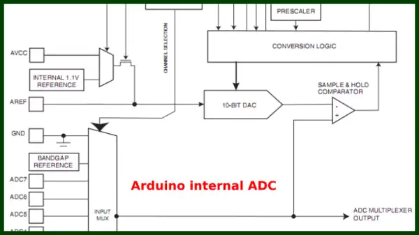
Fig. 1
Arduino Analog Digital Conversion Voltmeter
Earlier we learned how to use Arduino's PWM output with a LM358 voltage amplifier to make variable DC power supply. Now will combine that idea with a LM311 comparator to demonstrate how to read a voltage greater than 5-volts.
The idea is to understand how analog to digital conversion is done.
See Arduino Pulse-Width Modulation Digital to Analog Conversion
Fig. 1 shows the basic building block of most modern analog to digital converters in this case Arduino. This consists mainly of a voltage reference, a sample and hold comparator, and a digital to analog converter. (DAC).
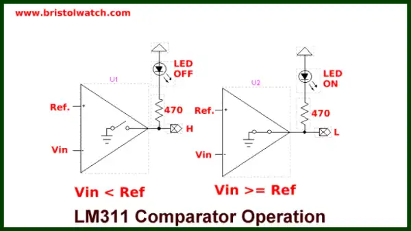
Fig. 2
In this case the DAC output is proportional to the binary input value from the control logic. At some point the binary value to voltage output from the DAC on the comparator inverting (-) will be equal to input voltage on the non-inverting (+) input. The output from the comparator will go HIGH or LOW, the count to the DAC is halted and returned as a 10-bit value with a analogRead() function.
There are two ways to control the input value to the DAC: ramp and successive approximation. In this demo I'll use the ramp method.
Fig. 2 shows how this would work with a LM311 type comparator.
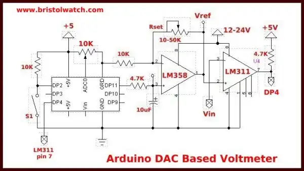
Fig. 3
In Fig 3 we are using a DAC based on the LM358 whose analog output is proportional to the 8-bit duly cycle of the PWM out of Arduino digital pin 11.
The PWM DAC output is connected to the LM311 non-inverting (+) input while the voltage to read is connected to the inverting (-) input of the comparator. The program uses a FOR loop counting from 0-255 and writing that value to control the duty cycle PWM output on DP11.
As the count increments or "steps" the voltage output increases in steps.
Between every count Arduino polls the status of DP4 which is connected to the LM311 output waiting for a low when the two inputs to the LM311 are equal. When this goes LOW the count is halted, the voltage value is calculated, then written to the LCD display.
The voltage range is set by Rset based on 5-volts (255 written to DP11) on the LM358 pin 3. The range can be no greater than the voltage on LM358 pin 8 minus 2-volts. Note the higher the range voltage the less accurate the resolution. A 0-10 volt range has a resolution of 10 / 255 = 39.2mV / step; at 20-volts it's 78mV / step. Rset can be used as a fine adjustment.
In this case I was reading 0-5 volts.
#include <Wire.h>
#include <LiquidCrystal_I2C.h>
// set the LCD address to 0x27
// 2-line 16-char numbered 0-15
LiquidCrystal_I2C lcd(0x27,16,2);

float voltage;
int i;

void setup(void) {
  pinMode(4, INPUT);
  lcd.init(); // initialize the lcd
  lcd.backlight();
  lcd.print("Arduino");

}

void loop(void) {
 i = 0;
 while(digitalRead(4))   {
   i++;
   analogWrite(11, i);
   delay(100);
 }

  lcd.setCursor(0,0);
  lcd.print("Count = ");
  lcd.print(i);
  lcd.print("  ");

  // scaler value = Vcc / 255
  voltage = .01961 * i;
  lcd.setCursor(0,1);
  lcd.print("Vin = ");
  lcd.print(voltage);

  delay(200);
  analogWrite(11, 0);
  lcd.home();
}
- Quick navigation of this website:
- Basic Electronics Learning and Projects
- Basic Solid State Component Projects
- Arduino Microcontroller Projects
- Raspberry Pi Electronics, Programming
- Comparator Theory Circuits Tutorial
- Zero-Crossing Detectors Circuits and Applications
- Improved AC Zero Crossing Detectors for Arduino
- Photodiode Circuits Operation and Uses
- Photodiode Op-Amp Circuits Tutorial
- Issues on Connecting MOSFETs in Parallel
- MOSFET DC Relays Using Photovoltaic drivers
- Optocoupler Input Circuits for PLC
- All NPN Transistor H-Bridge Motor Control
- Photo Voltaic Tutorial MOSFET Output Solid State Relays
- Optical Isolation of H-Bridge Motor Controls
- Design 10-Amp 2N3055 Based Power Switch
- TA8050P H-Bridge Motor Control
- Connecting Crydom MOSFET Solid State Relays
- H11L1, 6N137A, FED8183, TLP2662 Digital Output Optocouplers
- Arduino
- Arduino PWM to Analog Conversion
- Arduino Analog Digital Conversion Voltmeter
- Better Arduino Rotary Encoder Sensor
- Simple 3-Wire MAX6675 Thermocouple ADC Arduino Interface
- Hall Effect Magnetic Switches and Sensors
- Transistor-Zener Diode Regulator Circuits
- Build an Adjustable 0-34 volt power supply with the LM317
- Coils for Highly Selective Crystal Radio
- Neon (NE-2) Circuits You Can Build
- Understanding Xenon Flashtubes and Circuits
- LM2575 Simple Switching Voltage Regulators
- Simple 2 Transistor LED Flasher Circuit
- Generating High Voltage with an Inductor
Web site Copyright Lewis Loflin, All rights reserved.
If using this material on another site, please provide a link back to my site.