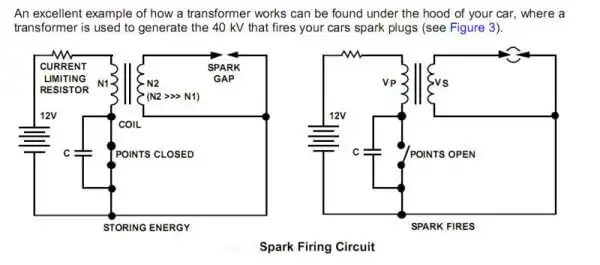
Fig. 1 Old style point condenser high voltage spark plug firing circuit.
Generating High Voltage with an Inductor
by Lewis Loflin
An easy way to generate a higher voltage from a low voltage DC source is with an inductor. Depending on the number turns of wire in the coil a 6 volt battery could produce a jolting 200V plus from a simple coil of wire. Fig. 1 illustrates how this was used to fire spark plugs in older vehicles. While that used a transformer we will use only a single coil. Understanding this explains the operation of boost switching regulators.
See my page Simple Switching Voltage Regulators.
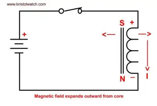
Fig. 2
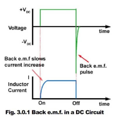
In Fig. 2 we have a DC source connected through a switch to an inductor. With the switch closed a current flows through the inductor in the direction shown creating an electromagnet. The polarity is dependant on the direction of current flow. The current flow creates an expanding magnetic field that holds back full current flow until the magnetic filed reaches maximum. In this case we say voltage leads the current, a property of inductive reactance. When the magnetic filed reaches max current I is max and if the switch is left closed the coil will get hot if it has a low DC resistance.
Note: Inductive reactance is the opposite of capacitive reactance where the current leads the voltage. Keep this in the back of one's mind as reactance applies when AC or pulsating DC is applied to an inductor or capacitor.
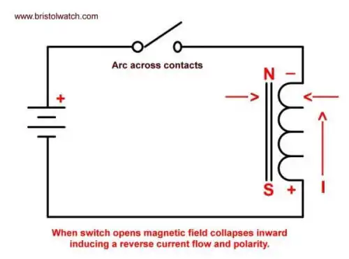
Fig. 3
In Fig. 3 the magnetic field around the electromagnet has reached maximum and we open the switch. If the contacts are visible one can see a small arc across the contacts if the coil has enough turns. The magnetic field created earlier collapses into the core in the opposite direction of the original magnetic field we created.
The rapid collapse of the magnetic field cuts across the copper windings inducing a high voltage spike of the opposite polarity of the DC source that created it. The direction of the magnetic field as it cuts across a coils determines polarity of the induced voltage. It was this induced high voltage that arced across the switch contacts, which is why a condenser (old name for capacitor) was used across the contacts (points) in Fig. 1 to extend their life before they had to be replaced.
This does not create more power than what was put into the coil. When the switch is closed we had low-voltage and high-current, when the switch was opened we induced a high-voltage, low-current pulse. The magnetic field stored energy that was "transformed" (thus the term transformer which often has two or more separate coil windings) current and voltage wise.

Fig. 4
An autotransformer has only on winding with one or more taps or extra connections.
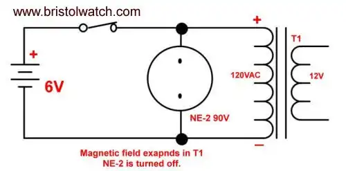
Fig. 5
In Fig. 5 we use a 6-volt battery and a power transformer used as an inductor. Power is supplied to the transformer primary though a switch and acts exactly as the inductor in Fig. 2 building up an intense magnetic field. Across the transformer winding is a NE-2 lamp that operates at 90 volts before it will begin to conduct. It stays off at 6-volts.
Also see Neon NE-2 Circuits You Can Build
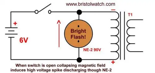
Fig. 6
In Fig. 6 when we open the switch instead of arching across the contracts the high voltage spike discharges though the NE-2 lamp producing a brief, intense purple-orange flash. Note once again the induced voltage polarity is opposite of the voltage that created it.
This concludes this brief introduction on inducing higher voltages from lower voltage DC sources. These ideas are used in boost switching voltage regulators to create higher and/or inverted output voltages. The mechanical switch is replaced with solid state bipolar or MOSFET transistors.
We will be using the LM25XX series of simple switching regulators and an Arduino demo switching regulator using pulse-width-modulation.
- Operation switching power supplies and transformer connection tutorials:
- Generating High Voltage with an Inductor
- Arduino Buck Switching Voltage Regulator Demo Only
- Switching Regular Configuration Review
- LM2575 Simple Switching Voltage Regulators
- Voltage Buck-Boost Transformer Connections Tutorial
Other Circuits
- Hall Effect Magnetic Switches and Sensors
- Transistor-Zener Diode Regulator Circuits
- Build an Adjustable 0-34 volt power supply with the LM317
- Coils for Highly Selective Crystal Radio
- Neon (NE-2) Circuits You Can Build
- Understanding Xenon Flashtubes and Circuits
Web site Copyright Lewis Loflin, All rights reserved.
If using this material on another site, please provide a link back to my site.