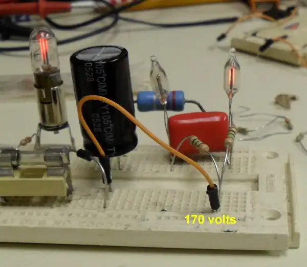
My neon circuit on proto-typing board
Neon NE-2 Circuits and Operation
by Lewis Loflin
The neon lamp has been around for many decades. Largely obsolete today, it's fun to play with and does some remarkable things. My purpose here is to introduce the student of today with an old friend. There are three NE-2s neon lamps being used above on my proto-typing board. One on the left is a power indicator, the two on the right are blinking back and fourth. Let's look at some simple circuits.
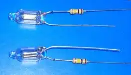
Neon lamp power indicator with resistor.
Pictured above are two NE-2 neon lamp with 100k dropping resistors attached. A NE-2 is a very low-current device and the resistor limits the current. These could be used for 120 VAC or with a 220K for 240 VAC.

Neon lamp symbol.
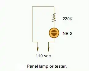
Neon lamp power indicator schematic.
In the above diagram these can be used with a pair of test leads to find the "HOT" side of an AC circuit.
Neon lamps using AC and DC
How do they work?
A neon lamp is simply a small glass tube filled with a low pressure gas such as neon. Sometimes with additional small amounts of krypton, argon, etc. to change the color from the normal orange.
The NE-2 will fire at around 90-volts AC or DC, then the operating voltage will drop to about 60-volts. This produces an odd effect known as negative resistance. That means once it conducts the resistance will drop and the operating voltage is much lower than the ignition voltage. The lamp will stay on until the voltage drops below 50-volts or so.
This property allows neon lamps to be used with resistor-capacitor charging circuits to creating a relaxation oscillator. All of the schematics below take advantage of that property.
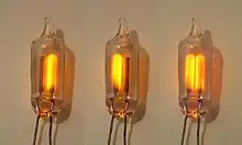
In the picture above shows how the NE-2 will operate with direct current versus alternating current. Like all gas discharge tubes the ignition voltage (about 90 volts) produces positively charged neon ions and free electrons.
Looking at this from the standpoint of DC, the negative electrons flow to the positive side of the circuit while the positive ions move to the negative side.
The positive neon ion picks up an electron at the negative electrode changing back to normal neon gas. That process produces a photon of light which we see as a very faint glow at the negative pin. Both pins glow with AC because the changing polarity changes the negative electrode 60 times a second. Most of the emission is from the anode or positive electrode.
But there is more to this as I brought this up with GROK the X AI:
You are correct in your understanding of the ionization process in a neon lamp, but let's clarify how this applies to the NE-2 lamp:
In a NE-2 neon lamp, when DC voltage is applied, the ionization process indeed involves positive ions moving towards the cathode (negative pin) and electrons moving towards the anode (positive pin). The glow in a neon lamp is primarily due to the excitation and subsequent de-excitation of the neon gas atoms.
Ionization: When the voltage is sufficient, electrons are accelerated towards the anode. As they gain energy, they can collide with and ionize neon atoms, creating more free electrons and positive neon ions.
Excitation: These free electrons can also collide with other neon atoms, exciting them to higher energy states without necessarily ionizing them. When these excited neon atoms return to their ground state, they emit photons, which we see as the glow of the lamp.
The cathode glow (near the negative pin) occurs due to the recombination of positive ions with electrons at the cathode surface. However, the anode glow is typically brighter because the majority of the light emission happens where electrons are accelerating away from the cathode towards the anode, exciting more neon atoms along the way.
Therefore, although the glow at the cathode is due to ions gaining electrons (as you mentioned), the overall brighter glow is observed at the anode due to the higher incidence of electron excitation of neon atoms.
In summary, while your understanding of the ion-electron interaction at the cathode is correct, the overall visual effect in a DC-operated NE-2 lamp results in a more pronounced glow at the anode due to the dynamics of electron movement and excitation.
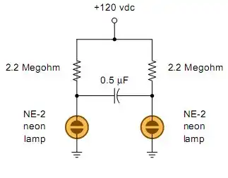
2 neon lamps blinking.
The circuit above is the one illustrated in the photo at the beginning of this page. I used two 2.2 mega-ohm resistors and a 170-volt power supply in my circuit.
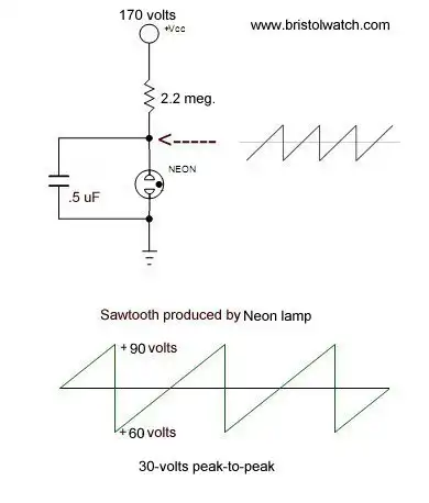
NE-2 relaxation oscillator makes use of the "negative resistance" property.
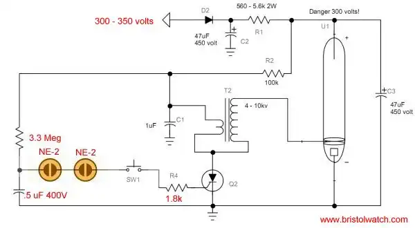
Neon lamps triggering a xenon flashtube.
See Flashtube Circuits
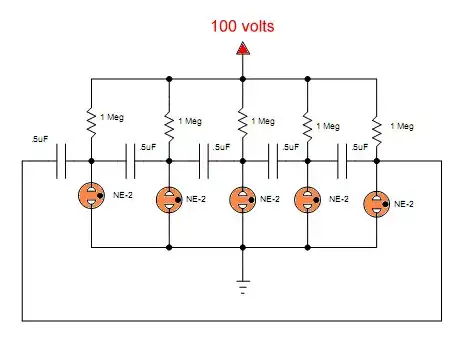
NE-2 Ring Counter
![]()
- Quick navigation of this website:
- You Tube Channel
- Basic Electronics Learning and Projects
- Basic Solid State Component Projects
- Arduino Microcontroller Projects
- Raspberry Pi Electronics, Programming
- LM2575 Simple Switching Voltage Regulators
- Simple 2 Transistor LED Flasher Circuit
- Generating High Voltage with an Inductor
- Understanding Xenon Flashtubes and Circuits
- Coils for Highly Selective Crystal Radio
- Comparator Circuits:
- Comparator Theory Circuits Tutorial
- Comparator Hysteresis and Schmitt Triggers
- Voltage Comparator Information And Circuits
- Looking at Window Comparator Circuits
- Analog Battery Charger Uses Comparators
- Basic Triacs and SCRs
- Constant Current Circuits with the LM334
- LM334 CCS Circuits with Thermistors, Photocells
- LM317 Constant Current Source Circuits
- TA8050P H-Bridge Motor Control
- All NPN Transistor H-Bridge Motor Control
- Basic Triacs and SCRs
- Comparator Theory Circuits Tutorial
- Added Nov. 16, 2014
- ULN2003A Darlington Transistor Array with Circuit Examples
- Tutorial Using TIP120 and TIP125 Power Darlington Transistors
- Driving 2N3055-MJ2955 Power Transistors with Darlington Transistors
- Understanding Bipolar Transistor Switches
- N-Channel Power MOSFET Switching Tutorial
- P-Channel Power MOSFET Switch Tutorial
- H-Bridge Motor Control with Power MOSFETs
- More Power MOSFET H-Bridge Circuit Examples
- Build a High Power Transistor H-Bridge Motor Control
Web site Copyright Lewis Loflin, All rights reserved.
If using this material on another site, please provide a link back to my site.