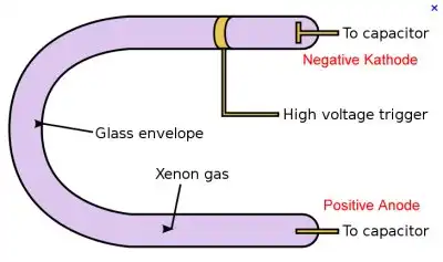
Fig. 1 Basic construction of a xenon flashtube.
Understanding Xenon Flash Tube Circuits
by Lewis Loflin
See You Tube Video on flash tubes.
A flashtube, also called a flash lamp, is an electric arc lamp designed to produce extremely intense, incoherent, full-spectrum white light for very short durations. Flashtubes are made of a length of thin glass tubing with electrodes at either end and are filled with a gas that, when triggered, ionizes and conducts a high voltage pulse to produce intense light. Flashtubes are used mostly for photographic purposes but are also employed in scientific, medical and industrial applications such as lasers.
- Unijunction Transistor SCR Photo Flash Control Circuit
- Understanding Unijunction Transistors Theory Operation
The flash lamp comprises a hermetically sealed glass tube, which is filled with xenon, and electrodes to carry electrical current to the gas. Additionally, a high voltage power source is necessary to ionize the gas. A charged capacitor is usually used for this purpose so as to allow very speedy delivery of very high electrical current when the lamp is triggered. (See fig. 1 above.) Flashtubes require high operating and triggering voltages and caution must be observed when using them.
The glass envelope is often made of fused quartz, borosilicate, or Pyrex. The electrodes protrude into each end of the tube. For low electrode wear the electrodes are usually made of tungsten, which has the highest melting point of any metal. Cathodes are often made from porous tungsten filled with a barium compound and the structure of cathode has to be tailored for the application. The cathode undergoes destruction from positively charged xenon ion bombardment. Anodes are usually made from pure tungsten.
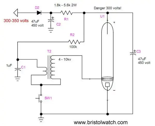
Fig. 2
Fig. 2 shows the thee main components of a flashtube circuit. This consists of a high voltage power supply, the flashtube itself, a high voltage trigger transformers, and a photoflash capacitor.
The tubes I used required 300 volts to operate correctly. One can use an inverter, a device that steps up a low voltage battery to a high voltage (this is used in cameras), or a voltage doubler circuit for a 120-volt AC line. I used a homemade inverter circuit using a 12-volt center-tapped transformer as shown in the photos below. See the following:
Capacitor C1 is charges through resistor R2. When the switch is pressed C1 quickly discharges though T2 creating a high voltage pulse that ionizes the gas in the tube, causing C3 to discharge through the tube, thus crating a bright flash.
Note that while a standard electrolytic capacitor can be used, specially made photoflash capacitors should be used. They can withstand the high discharge rate. Resistor R1 must be used to keep the power supply from swamping and destroying the tube. In my setup C3 charges up to 330 volts and discharges down to 100 volts.
Using a photoflash capacitor that's too large can destroy the tube from overheating and thermal shock. The trigger transformer is usually matched to the tube.

Using an SCR allows the use of low-voltage electronics to control the flash. Make note of gate sensitivity.
See Basic Triacs and SCRs
Click image for larger view.
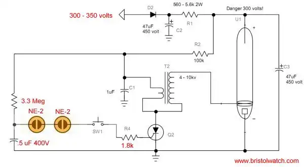
Another variation of triggering an SCR through one or two NE-2 neon lamps.
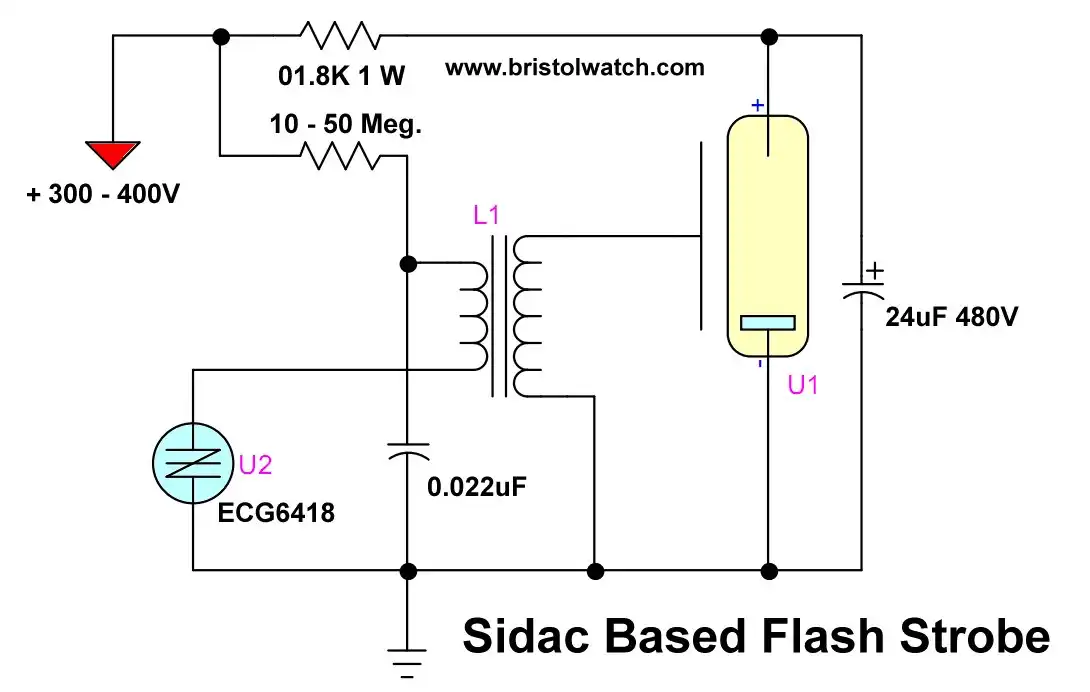
Here we use a Sidac. The flash rate is controlled by R2 and C1.
See How to use SIDACs and their operation
Click for larger image.
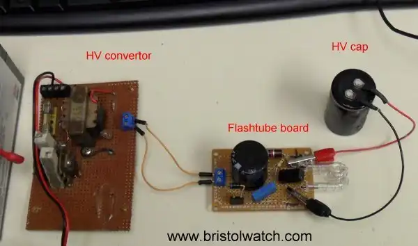
My experimental flashtube test setup.
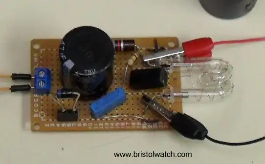
Closer view of my flashtube board.
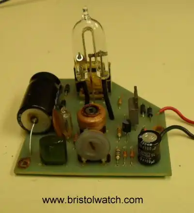
A board pulled from a flasher used on a state truck.
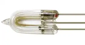
Picture of a horseshoe shaped flashtube. Flashtubes come in a number of shapes and sizes.
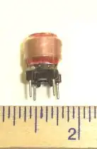
One type of trigger transformer.
- Quick navigation of this website:
- Basic Electronics Learning and Projects
- Basic Solid State Component Projects
- Arduino Microcontroller Projects
- Raspberry Pi Electronics, Programming
Also see Simple DIAC Based Relaxation Oscillator Pulse Generator
- Connecting Transformers in Series-Parallel
- Build an Adjustable 0-34 volt power supply with the LM317
- AC Power Supply Rectification
- Basic Power Transformers
- Transistor-Zener Diode Regulator Circuits
- Tips for the LM78XX Series Voltage Regulators
- Bi-Polar Power Supplies
- Connecting Series-Parallel Batteries
- Build Autotransformer-Variac AC and DC Power Supply
- Understanding Unijunction Transistors Theory Operation
- Unijunction Transistor SCR Photo Flash Control Circuit
- Basic Triacs and SCRs
- Solid State AC Relays with Triacs
- Light Activated Silicon Controlled Rectifier (LASCR)
- Photo Detector Devices:
- Photodiode Circuits Operation and Uses
- Photodiode Op-Amp Circuits Tutorial
- Photo Voltaic Tutorial MOSFET Output Solid State Relays
- Added Nov. 16, 2014
- ULN2003A Darlington Transistor Array with Circuit Examples
- Tutorial Using TIP120 and TIP125 Power Darlington Transistors
- Driving 2N3055-MJ2955 Power Transistors with Darlington Transistors
- Understanding Bipolar Transistor Switches
- N-Channel Power MOSFET Switching Tutorial
- P-Channel Power MOSFET Switch Tutorial
- More Power MOSFET H-Bridge Circuit Examples
- Build a High Power Transistor H-Bridge Motor Control
Web site Copyright Lewis Loflin, All rights reserved.
If using this material on another site, please provide a link back to my site.