Fig. 1
DIAC Relaxation Oscillator Pulse Generator
by Lewis Loflin
Define relaxation oscillator: "an oscillator in which sharp, sometimes aperiodic oscillations result from the rapid discharge of a capacitor or inductance."
This is an updated version of my webpage DIAC Circuits and Uses.
To briefly review a DIAC is a two-terminal solid state device used mainly for triggering other devices such as triacs. While often referred to as a "diode" it is more related triacs and silicon controlled rectifiers. It is not a diode.
One definition of a DIAC is:
A DIAC semiconductor is a full-wave or bidirectional Thyristor. It is triggered from a blocking state to a conduction state for either polarity of applied voltage whenever the amplitude of applied voltage exceeds the breakover voltage of the DIAC.
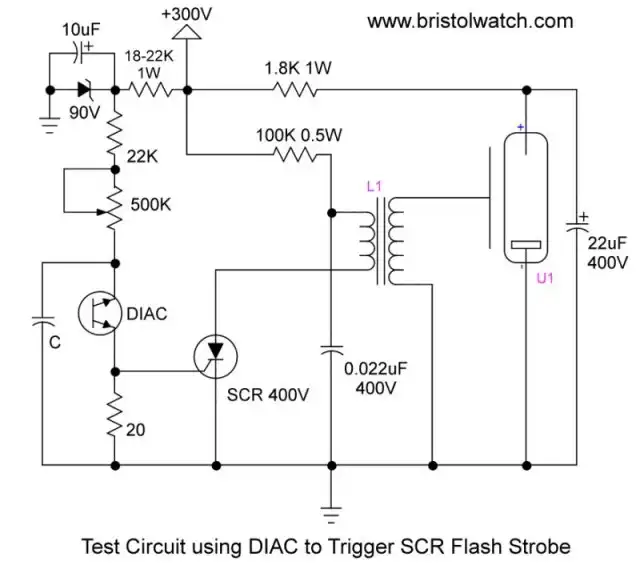
Fig.1 uses a DIAC RC circuit to trigger an SCR to operate a flash tube circuit. For more in flash tube circuits see Understanding Xenon Flashtubes and Circuits
This is the same circuit with modifications that used a Unijunction Transistors to trigger an SCR.
See Unijunction Transistor SCR Photo Flash Control Circuit.
My main emphasis here is using a DIAC as a relaxation oscillator. I'll discuss two differing parts, calculations, etc. DIACs are used for:
DIACs are used to trigger Triacs and SCRs in phase control circuits for lamp dimming, universal motor speed control, and heat control. They are used also for triggering transistors in solid state ballast lighting controls.
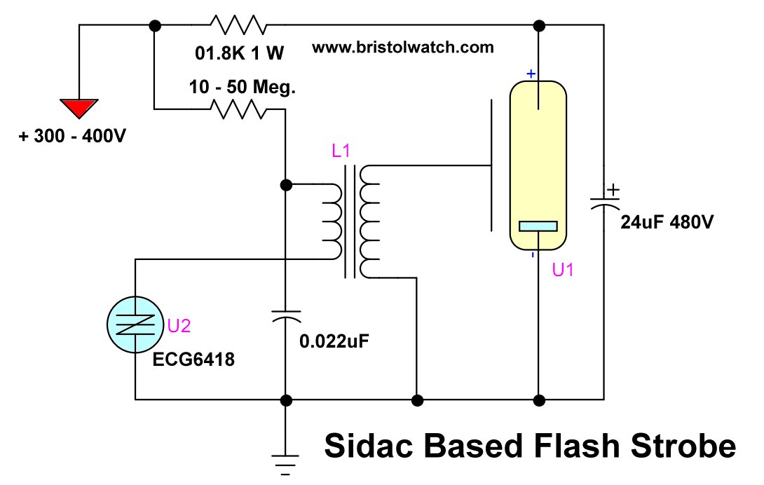
In some ways a DIAC is similar to a SIDAC but differs in two important ways. First a DIAC is a very low power device. A DIAC typically operates (known as break over voltage) at 32V at low current.
A SIDAC operates at hundreds of volts at heavy current. I can drive the flashtube transformer directly without the use of the SCR in Fig. 1.
See the following:
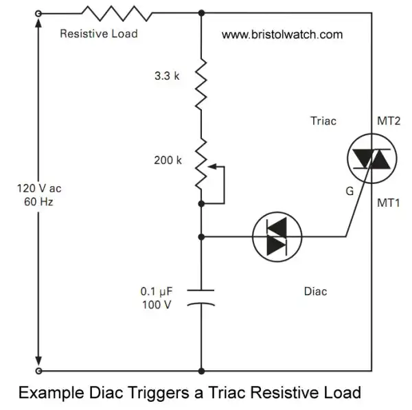
Fig. 2
Typical DIAC circuit used in lamp dimmers. Here we drive a triac and the timing is based the resistance of the 3.3K resistor, 200K pot, and the 0.1uF capacitor.
Note this came from the HT32 DIAC spec sheet.
But it more complicated as I will show below. We want the generated trigger pulse to vary (at 60Hz) from ~0-8.3mSec from the AC zero-crossing point.
In other words we want to turn on triac from 0-90 degrees per half cycle.
For more on zero-crossing and AC switching see the following:
- Improved AC Zero Crossing Detectors for Arduino
- Zero-Crossing Detectors Circuits and Applications
- Basic Triacs and SCRs

Fig. 3A

Fig. 3B
Fig. 3A and 3B illustrate the needed power supplies for the rest of the test circuits. There are based on my transformer series-parallel tutorial. One will need at least a single 40V or greater supply. I used mainly the 90V supply.
See Connecting Transformers in Series-Parallel.
See Youtube video How to Connect Series-Parallel Transformers.

Fig. 4A
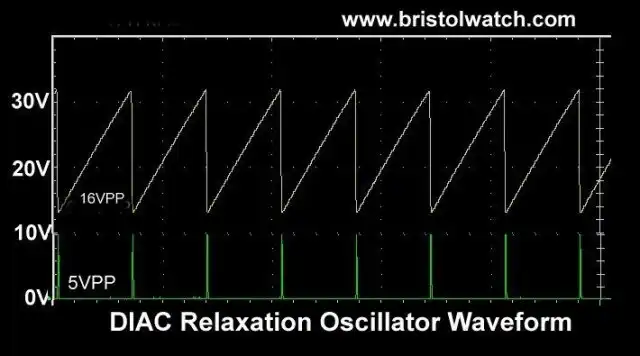
Fig. 4B
My test circuit is illustrated in Fig. 4A and the output waveforms are shown in Fig. 4B.
Channel 1 on the digital oscilloscope displays the sawtooth waveform while channel 2 the narrow "spike" pulse from the 20 Ohm resistor.
The spike pulse is used trigger the SCR in Fig. 1. This is created by the capacitor discharge.
The ramp or sloped waveform comes from the capacitor C1 charged through 250K pot and 22.5K resistor.
I used two different parts a DB3 and a HT32. The DB3 sells for pennies on Ebay and the HT32 are new old stock in my parts collection.
The spike is created when capacitor C1 exceeds the breakover voltage (VBo) of the diac in both devices ~32V. The capacitor discharges though the diac and 20 Ohm resistor.
Both diacs are low power devices. The spec sheets specify 2 amps max with a 10uSec and 20uSec. pulse. In reality they are rated around 300mA.
Again these are not high frequency devices. I got one to work at 23KHz but very unstable. Reliable use is under 2000 Hz. in my view.
Below are the test results I got using the two diacs in the very same circuit settings with a 90V power supply.
Device: HT32, C1 = 0.2uF, R = 22.5K; Frequency: 1.475KHz.
C1 = 0.2uF, R = 266K; Frequency: 137Hz.
In both cases sawtooth was 9.4VPP, spike 5VPP.
I calculated a correction factor of 0.14. This was derived by the reciprocal of the frequency divided by C1 and R.
I did this for both frequencies and took the average. So the formula is F = 1 / 0.14RC.
The frequency is based not only on R and C1 but the breakover voltage of the diac and the voltage at turnoff when the charge cycle begins again.
The HT32 breakover voltage is 32V but the discharge voltage drops to about 23V before the cycle begins again. The supply voltage also plays into this.
Now we turn to the DB3 diac and things get interesting.
Device: DB3, C1 = 0.2uF, R = 22.5K; Frequency 874Hz.
C1 = 0.2uF, R = 266K, Frequency = 76Hz.
Here is why the frequencies differ in the very same circuit:
Sawtooth 18VPP and spike 6VPP.
While both diacs breakover at 32V the DB3 discharge voltage is nearly double that of the HT32. That will cut the frequency nearly in half due the longer recharge time.
Thus the correction factor for the DB3 is ~0.24. Frequency = 1 / 0.24RC.
![]()
- Quick navigation of this website:
- You Tube Channel
- Basic Electronics Learning and Projects
- Homepage Lewis Loflin
- Follow on X
- Skeptic Site
- Religion 1
- Religion 2
- Coils for Highly Selective Crystal Radio
- Neon (NE-2) Circuits You Can Build
- Understanding Xenon Flashtubes and Circuits
- Hall Effect Magnetic Switches and Sensors
- Transistor-Zener Diode Regulator Circuits
- Build an Adjustable 0-34 volt power supply with the LM317
- Simple 2 Transistor LED Flasher Circuit
- LM2575 Simple Switching Voltage Regulators
- LM317 Constant Current Source for Lighting LEDs
- IGBT Based High Voltage H-Bridge DC Motor Control
- Arduino Controlled IR2110 Based H-Bridge HV Motor Control
- Understanding Unijunction Transistors Theory Operation
- Arduino Measures Current from Constant Current Source
- Constant Current Source Theory Testing
- Review Ohm's Law for Trouble-Shooting CCS Circuits
- Arduino Power Magnetic Driver Board for Stepper Motors
- Arduino Controlled Power Constant Current Source
- Theory and Operation of Capacitors
Related video to above:
- Measure Current from Constant Current Source with Arduino
- Constant Current Source Multimeter Trouble Shooting
- Ohm's Law Review for Constant Current Source
- Arduino Unipolar Stepper Motor Driver Board with Arduino Code
- Arduino Controlled Constant Current Source
- LM317 Adjustable Current Boost Power Supply
- Constant Current Circuits LM334, LM317
- Build LM317 0-34 Volt Power Supply
- LM334 Constant Current Source with Resistive Sensors
- LM317 High Power Constant Current Source Circuit
- LM317 Constant Current Source Circuits
- Test SCRs and Triacs
- Basic MOSFET Transistor Test Circuits
- High Voltage MOSFET Switching Circuits
- 3 Amp LM741 Op-Amp Constant Current Source
- Current Limiter Testing of Zener Diodes
- Current Limiter for Opto-Coupler Inputs
- LM317 CCS for Light Emitting Diodes
Web site Copyright Lewis Loflin, All rights reserved.
If using this material on another site, please provide a link back to my site.