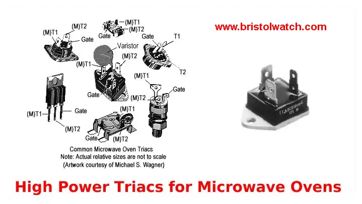
Basic Triacs and SCR Projects and Circuits
by Lewis Loflin
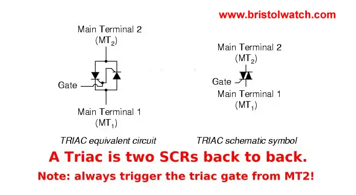
This page will discuss basic triacs and SCRs. A triac is a bidirectional, three-terminal dual, back-to-back Thyristor (SCR) switch. This device can switch the current in either direction by applying a small current of either polarity between the gate and main terminal two.
The triac is fabricated by integrating two Thyristors in an inverse parallel connection. It is used in AC applications such as light dimming, motor-speed control, etc. Triacs can also be used in micro-controller power control with a phase synchronization circuit.
If one is not familiar with diodes and AC rectification see the following:
Turning a Diode On/Off
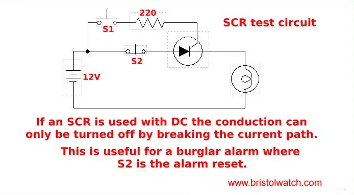
Pictured above is a silicon controlled rectifier (SCR) or thyristor. It's a diode with a "gate." An SCR not only conducts in one direction like any other diode, but the gate allows the conduction itself to be cut on and off.
When the ON switch is pressed, the SCR is turned on, and current flows from negative to positive through the SCR and load. Once turned on, the SCR will remain on until the Off switch is pressed, breaking the current path.
Note that the ON switch is referred to as 'normally open' (N.O.) and makes (closes) a connection when pressed. The OFF switch is referred to as 'normally closed' (N.C.) breaks (opens) the connection when pressed. Both of these are push button switches.
In the circuit above the Load is a DC lamp. Press the S1 switch and the turns on and will continue to stay on until the S2 switch is pressed.
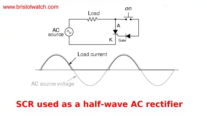
In this example we have placed a diode in series with the gate on/off switch. When one presses the ON switch, the motor will run, the light will come on, etc. When the switch is released, the power is killed without use of an OFF switch.
This is because the AC input goes back to zero volts at 180 and 360 degrees shutting off the SCR. And as a diode, the SCR only conducts one-half the cycle.
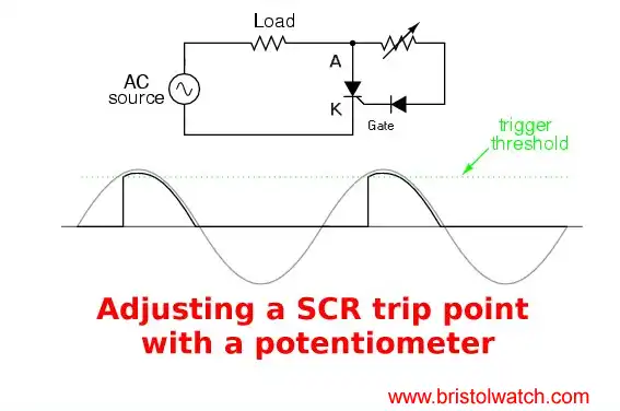
In this circuit example we have placed variable resistor (potentiometer) in series with the gate diode. (This was also known as an old style volume control knob.) By "turning the knob" we can alter the trip point in turning on the SCR only part of the half-cycle or if enough resistance, turn the SCR off.
This illustrates to process with full-wave unfiltered D.C.
In another note we can control full-wave pulsating unfiltered DC with a thyristor. Also see Basic AC Rectification and Filtering
For more see What is a Light Activated Silicon Controlled Rectifier? (LASCR) and H11C6 SCR opto-Coupler data sheet. (PDF file)

Above is a practical SCR test circuit. The lamp will come on only when Sw3 is pressed. The lamp will be at half brightness because the SCR acts as a half-wave rectifier. R4 can be in the range of 100 to 470 ohms.
The lamp should be completely off unless the switch is pressed or the device is defective. (Fully or partially shorted.)
This circuit is also good for comparing different SCRs of the same part number. For example I once had a problem circuit board with six SCRs, but one SCR of the six when working switched on at a very different trigger voltage than the other five.
The lamp was a different brightness level than the other five. Replacing that one SCR fixed that very expensive circuit board.
Introduction to Triacs
A triac is a solid state AC switch. A small current on the gate terminal can switch very large AC currents. Think of a triac as two back-to-back SCRs where the cathode of one SCR is connected to the anode of the other and vise-versa.
The gates are connected together. Because we have the two SCRs type configuration allows the switching of both half-cycles.
Note: I have seen paper examples of using 2 SCRs back to back as a triac, but this may not work the same! Be wary of this.
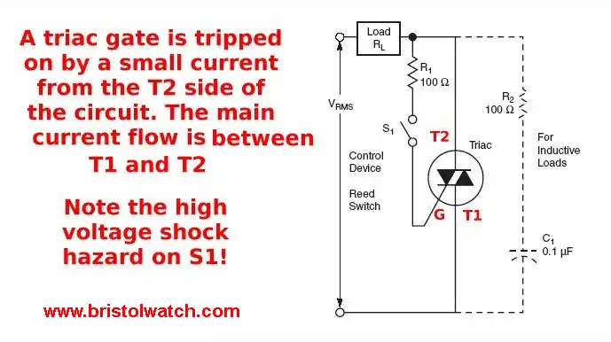
In the above example closing the switch will cut on the triac. The idea is to use a small low-power switch to control high power devices such as motors or heaters. The danger here is the high voltage AC is on the switch itself.
This can also be a big problem for solid state controllers unless they use a small relay, which some microwave do just that.
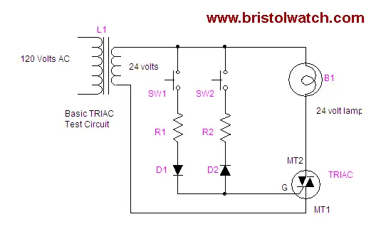
Above is a practical TRIAC test circuit. Press either switch and the lamp will come on at half brightness. Press both together full brightness.
This allows testing of both SCR sides individually. The brightness should be the same for both sides or the TRIAC is defective. With no switch pressed, lamp should be totally off. R1 and R2 should be in the range of 100 to 470 ohms.
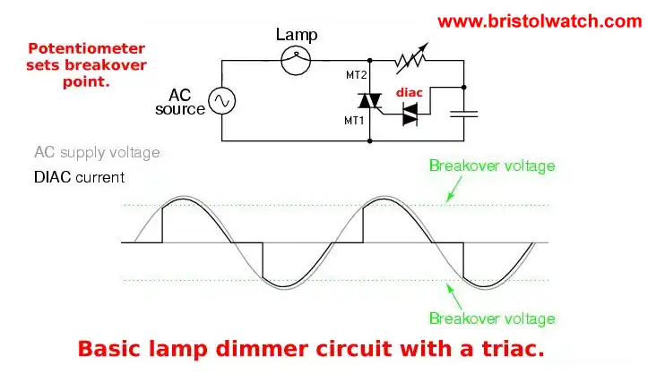
Best response triac circuit with a diac.
The key to successfully triggering a triac is to make sure the gate receives its triggering voltage from the main terminal 2 side of the circuit (the main terminal on the opposite side of the TRIAC symbol from the gate terminal).
Identification of the Mt1 and Mt2 terminals must be done via the TRIAC's part number with reference to a data sheet or book.
The DIAC, or 'diode for alternating current', is a trigger diode that conducts current only after its breakdown voltage has been exceeded momentarily. When this occurs, the resistance of the DIAC abruptly decreases, leading to a sharp decrease in the voltage drop across the DIAC itself thus producing a sharp increase in current flow through the triac gate.
This assures a fast, clean cut on of the TRIAC. The DIAC remains in its conduction mode until the voltage drops to a very low value far below the trigger voltage.
This is called the holding current. Below this value, the diac switches back to its high-resistance (off) state. This behavior is bidirectional, meaning typically the same for both the positive and negative half cycles.
Most DIACs have a breakdown voltage around 30 V. In this way, their behavior is somewhat similar to (but much more precisely controlled and taking place at lower voltages than) a neon lamp.
DIACs have no gate electrode, unlike some other Thyristors. Some TRIACs contain a built-in DIAC in series (I've never seen one in the field) with the TRIAC's "gate" terminal for this purpose. DIACs are also called symmetrical trigger diodes due to the symmetry of their characteristic curve.
Because DIACs are bidirectional devices, their terminals are not labeled as anode and cathode but as A1 and A2 or Mt1 ("Main Terminal") and Mt2. Most specification sheets don't bother to label A1/A2 or Mt1/Mt2.
Also see How to Test a DIAC

Commercial lamp dimmer in 220 volt countries. Br100 is a diac.
A diac provides cleaner switching for the triac. Diacs are specialized Shockley diodes connected back-to-back.
Snubbers
A snubber circuit (usually of the RC type) is often used between MT1 and MT2. Snubber circuits are used to prevent premature triggering caused for example by voltage spikes in the AC supply or those produced by inductive loads such as
motors.
Also, a gate resistor or capacitor (or both in parallel) may be connected between gate and MT1 to further prevent false triggering. That could increase the required trigger current and perhaps a delay in turnoff as the capacitor discharges.
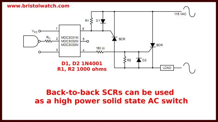
In this circuit above the "hot" side of the line is switched and the load connected to the cold or ground side. The 100-ohm resistor and 0.1uF capacitor are for snubbing of the triac. These components must be used with inductive loads such as motors, contactors, etc.
For more on the above opto-coupler see moc30xx series opto-isolator (pdf file)
- Quick navigation of this website:
- Basic Electronics Learning and Projects
- Basic Solid State Component Projects
- Arduino Microcontroller Projects
- Raspberry Pi Electronics, Programming
- ULN2003A Darlington Transistor Array with Circuit Examples
- Tutorial Using TIP120 and TIP125 Power Darlington Transistors
- Driving 2N3055-MJ2955 Darlington Transistors
- Understanding Bipolar Transistor Switches
- N-Channel Power MOSFET Switching Tutorial
- P-Channel Power MOSFET Switch Tutorial
- H-Bridge Motor Control with Power MOSFETs
- Arduino Controlled IR2110 Based H-Bridge HV Motor Control
- IGBT Based High Voltage H-Bridge DC Motor Control
- More Power MOSFET H-Bridge Circuit Examples
- Build a High Power Transistor H-Bridge Motor Control
- Related:
- N-Channel Power MOSFET Switching Tutorial
- P-Channel Power MOSFET Switch Tutorial
- Test Power MOSFET Transistors, Observations
- Issues on Connecting MOSFETs in Parallel
- Basic MOSFET Transistor Test Circuits
- High Voltage MOSFET Switching Circuits
- Why Your MOSFET Transistors Get Hot YouTube
- Issues on Connecting MOSFETs in Parallel YouTube
- Simple Circuits for Testing MOSFET Transistors YouTube
See the following spec sheets:
- Basic Triacs and SCRs
- Constant Current Circuits with the LM334
- LM334 CCS Circuits with Thermistors, Photocells
- LM317 Constant Current Source Circuits
- TA8050P H-Bridge Motor Control
- All NPN Transistor H-Bridge Motor Control
- Basic Triacs and SCRs
- Comparator Theory Circuits Tutorial
Web site Copyright Lewis Loflin, All rights reserved.
If using this material on another site, please provide a link back to my site.