
Fig. 1
Diac Waveform Generator, Trigger Circuits
A DIAC is a two-electrode bidirectional "trigger diode" which can be switched from off-state to the on-state by either polarity of an applied AC voltage.
Again the terminal designations MT1 and MT2 are arbitrary. The switching from off-state to on-state is achieved by exceeding the avalanche break over voltage in either direction.
An unusual characteristic is once the DIAC goes into conduction, the resistance drops rapidly sometimes called negative resistance. Stating this another way, "negative resistance characteristic, that is, voltage decreases with the increase in current."
Many claim DIACs have a three-layer structure with breakdown voltage around 30-45 volts. I dispute the three layer structure. DIACs have no gate electrode and are commonly used to trigger TRIACs.
DIACs are also called symmetrical trigger diodes due to the symmetry of their characteristic curve. Because DIACs are bidirectional devices, their terminals are labeled MT1 ("Main Terminal") and MT2. Ref. Wiki.
So much for theory, how does one check as DIAC? The only thing a volt-ohm meter will check is if the DIAC is shorted in the diode check mode. It will read "open" both ways otherwise. To really check a DIAC we need to apply a voltage and note where the DIAC conducts and turns off.
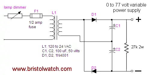
Fig. 2 variable power supply.
The Power Supply
The first thing we need is a variable D.C. power supply from 0-50 volts or more. In my industrial electricity class we do have a variable A.C power supply for 0-22 volts AC. If one is at home or has no access to a supply, one can be easily built.
Show above in Fig. 1 is a "home brew" test circuit. The "lamp dimmer" is simply a common dimmer circuit for room lighting available at any Lowe's or Home Depot. This should have a knob or slider control. This is used with a Radio Shack 120 to 24-volt transformer to form a variable A.C. supply. D1, D2, C1, C2 form a half-wave voltage doubler and filter. It wouldn't hurt to wire a 27k bleeder resistor across C1 and C2.
Perform the Test
If one has a 0-50 volt D.C. supply, all they need is U1 and R1. R1 is a 4.7k resistor.
Step 1: Set the voltage out to 0 volts as measured across TP1 and TP3. Connect a D.C. volt meter across TP2 (red lead) and TP3 (black lead). Slowly increase the voltage. In the case of my test, the diac voltage appeared across R1 at about 30 volts on TP1 then quickly jumped up to between 10-15 volts.
This is due to the fact a DIAC displays a negative resistance property once the break-over voltage is achieved the resistance will drop rapidly to some lower value. The voltage should steadily increase across R1 as the voltage from the supply is turned up. Don't go past 40-50 volts.
Step 2: Slowly turn the supply down and note the reading across R1. Between 15 and 25 volts in my case voltage suddenly dropped to zero.
Step 3: Reverse the DIAC, repeat steps 1 and 2. One should get the same results.
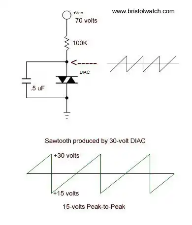
Fig. 3 DIAC connected as relaxation oscillator
A DIAC Sawtooth Oscillator
If one has an oscilloscope then we can connect the test DIAC to form a relaxation oscillator. In the circuit above the capacitor will charge through the 100k resistor.
When the charge voltage reaches the DIAC break over voltage the capacitor will quickly discharge through the DIAC until the voltage goes below the DIAC holding current, at which time the DIAC will turn off. At that point (around 15 volts) the capacitor will charge again and repeat the process.
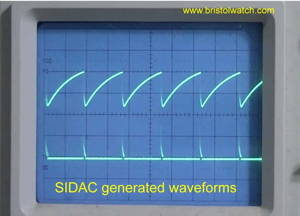
Fig. 4 Sawtooth waveform displayed on an oscilloscope.
Click for larger image.
In Fig. 4 is the actual waveform produced by a Diac relaxation oscillator. With the vertical set to 5 volts per division, our waveform has a P-P voltage of 15 volts.
The period (thus frequency) from beginning of charge to discharge is dependant on the value of the capacitor and charge resistor. Leaving the charge resistor at 100k and turning the power supply to 70-volts, the following for period (p) was measured:
C = .015uF: p = .275 mSec.
C = .100uF: p = 3 mSec.
C = .220uF: p = 6 mSec.
C = .330uF: p = 8.4 mSec.
C = .560uF: p = 15 mSec.
The frequency of the sawtooth waveform is found by taking the reciprocal of the period. Note the peak-to-peak voltage stayed the same value regardless of which capacitor I used.
- Quick navigation of this website:
- Basic Electronics Learning and Projects
- Basic Solid State Component Projects
- Arduino Microcontroller Projects
- Raspberry Pi Electronics, Programming
Also see Simple DIAC Based Relaxation Oscillator Pulse Generator
- Connecting Transformers in Series-Parallel
- Build an Adjustable 0-34 volt power supply with the LM317
- AC Power Supply Rectification
- Basic Power Transformers
- Transistor-Zener Diode Regulator Circuits
- Tips for the LM78XX Series Voltage Regulators
- Bi-Polar Power Supplies
- Connecting Series-Parallel Batteries
- Build Autotransformer-Variac AC and DC Power Supply
- Understanding Unijunction Transistors Theory Operation
- Unijunction Transistor SCR Photo Flash Control Circuit
- Basic Triacs and SCRs
- Solid State AC Relays with Triacs
- Light Activated Silicon Controlled Rectifier (LASCR)
- Photo Detector Devices:
- Photodiode Circuits Operation and Uses
- Photodiode Op-Amp Circuits Tutorial
- Photo Voltaic Tutorial MOSFET Output Solid State Relays
- Added Nov. 16, 2014
- ULN2003A Darlington Transistor Array with Circuit Examples
- Tutorial Using TIP120 and TIP125 Power Darlington Transistors
- Driving 2N3055-MJ2955 Power Transistors with Darlington Transistors
- Understanding Bipolar Transistor Switches
- N-Channel Power MOSFET Switching Tutorial
- P-Channel Power MOSFET Switch Tutorial
- More Power MOSFET H-Bridge Circuit Examples
- Build a High Power Transistor H-Bridge Motor Control
Web site Copyright Lewis Loflin, All rights reserved.
If using this material on another site, please provide a link back to my site.