Fig. 1 Click for larger image.
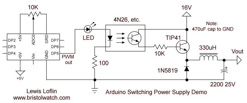
Arduino Buck Switching Voltage Regulator Demo
by Lewis Loflin
Note: this is NOT a practical circuit but for demonstration purposes only.
For more on pulse-width-modulation see Pulse Width Modulation Power Control
The purpose here is use Arduino's pulse-width-modulated to create a basic buck switching regulator. The output voltage is controlled by PWM duty cycle based on the position of a 10K potentiometer connected to ADC0. This serves as an introduction to buck regulators differing in no feedback circuit to control the output. The schematic is shown in Fig. 1.
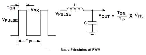
Fig. 2
Fig. 2 illustrates the use of a pulse-width-modulated voltage on the inductor-capacitor combination. Energy is stored in the capacitor and inductor magnetic field. The magnetic field expands to store energy during PWM on time the releases the energy during off time.
For more on how an indictor stores and release energy see Generating High Voltage with an Inductor. This circuit is a voltage step down circuit where Vout is less than Vin. The formula is duty cycle times peak voltage in.
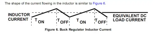
Fig. 3
Fig. 3 illustrates the inductor current. The energy is added during PWM on time and is released during PWM off time. There are two possible modes continuous where inductor current is flowing at all times and discontinuous where inductor of off part of the time.
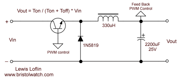
Fig. 4
Fig. 4 is a basic buck step down regulator circuit. We use a transistor switch whose on time is controlled by the PWM duty cycle. Energy is fed to a 330uH coil whose magnetic field expands - voltage and current are out of phase. During off time the magnetic field collapses reversing the polarity and feeding the current back though 1N5819 (known as a catch diode) high-speed Schottky switching diode that charges a 2200uF electrolytic capacitor.
An opto-coupler is used with a TIP41 NPN transistor acting as an electronic switch. We use no feedback circuits to regulate the output something all practical switching regulators employ.
See LM2575 Simple Switching Voltage Regulators.
Below is the Arduino code.
#define Apin 0
#define PWM_Pin 5

int i;

void setup() {
  // put your setup code here, to run once:
 //  pinMode(PWM_Pin, OUTPUT);
}

void loop() {
  i = analogRead(Apin) >> 2;  // same as  i/4
  analogWrite(PWM_Pin, i);
}
- Operation switching power supplies and transformer connection tutorials:
- Generating High Voltage with an Inductor
- Arduino Buck Switching Voltage Regulator Demo Only
- Switching Regular Configuration Review
- LM2575 Simple Switching Voltage Regulators
- Voltage Buck-Boost Transformer Connections Tutorial
Other Circuits
- Hall Effect Magnetic Switches and Sensors
- Transistor-Zener Diode Regulator Circuits
- Build an Adjustable 0-34 volt power supply with the LM317
- Coils for Highly Selective Crystal Radio
- Neon (NE-2) Circuits You Can Build
- Understanding Xenon Flashtubes and Circuits
Web site Copyright Lewis Loflin, All rights reserved.
If using this material on another site, please provide a link back to my site.