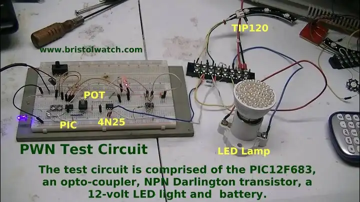
Fig. 1 Test setup using a Microchip 12F683 to demonstrate pulse width modulation.
Pulse Width Modulation Power Control
by Lewis Loflin
Here we will explore the concept of pulse-width modulation in particular as used by Arduino and Microchip PIC controllers. Our main focus is power control - by varying the "duty cycle" we can control power transfer to any number loads.
Pulse-width modulation (PWM) is a commonly used technique for controlling power made practical by modern electronic power switches. The average value of voltage (and current) fed to the load is controlled by turning the (transistor) switch between supply and load on and off at a fast pace. The longer the (transistor) switch is on compared to the off periods, the higher the power supplied to the load is.
The PWM switching frequency has to be much faster than what would affect the load, which is to say the device that uses the power...
The term duty cycle describes the proportion of 'on' time to the regular interval or 'period' of time; a low duty cycle corresponds to low power, because the power is off for most of the time. Duty cycle is expressed in percent, 100% being fully on.
The main advantage of PWM is that power loss in the switching devices is very low. When a switch is off there is practically no current, and when it is on, there is almost no voltage drop across the switch. Power loss, being the product of voltage and current, is thus in both cases close to zero. PWM works also well with digital controls, which ... can easily set the needed duty cycle.
Ref. https://www.princeton.edu/~achaney/tmve/wiki100k/docs/Pulse-width_modulation.html
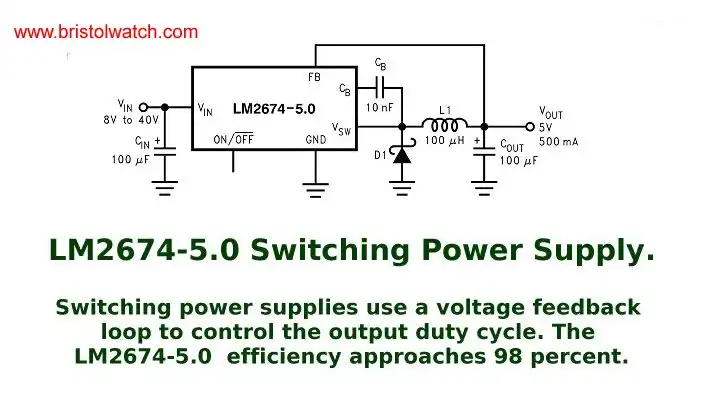
Fig. 2 LM2674-5.0 switching power regulator schematic.
Switching power supplies for example use a voltage feedback loop to control the output duty cycle. the LM2674-5.0 uses only a few external parts and unlike older series-pass voltage regulators such as a LM7805 efficiency approaches 98 percent.
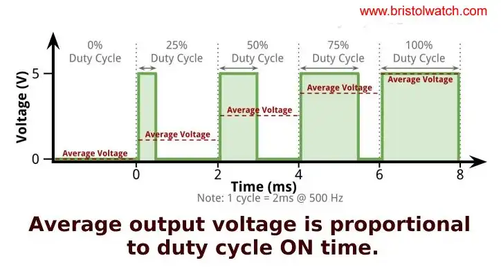
Fig. 3 Average voltage is proportional to duty cycle.
Pulse Width Modulation with Micro-Controllers
Micro-controllers such as Arduino have no concept of analog voltages - 1s and 0s or HIGH and LOW or GND and Vcc. While it's possible to use software loops to create a PWM output most of the time we employ hardware counters and dividers. Time is something a uPC does understand. Through a low-pass filter we can create an analog voltage from a pulse-width modulated output, other times we use duty to control the average voltage.
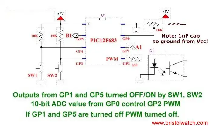
Fig. 4 Mircochip PIC PIC12F683 test setup.
This test circuit (Fig. 1) employs a Mircochip PIC PIC12F683 using its analog-to-digital converter (ADC) taking the analog value of a potentiometer converting the 0-5V reading into a 10-bit value from 0-1023. That 10-bit value is sent to pulse-width-modulation module at pin GP2.
That value sets the duty cycle (on time vs. period) of a 250Hz square wave generated by an internal timer. Period = 1/F = 1/250 = 4mSec.
For more on the PIC12F683 see Introduction to PIC12F683 Programming.
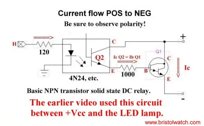
Fig. 5
The test circuit uses the PIC12F683, to control a the average voltage through an opto-coupler NPN Darlington transistor combination to a 12-volt LED light and 12-volts battery. The opto-coupler serves to isolate the 12-volt circuit from the 5-volt micro-controller circuit.
At this let's look at the output waveform across a LED lamp starting from fully to fully off. The output frequency is 250Hz and the period is 4mSec.
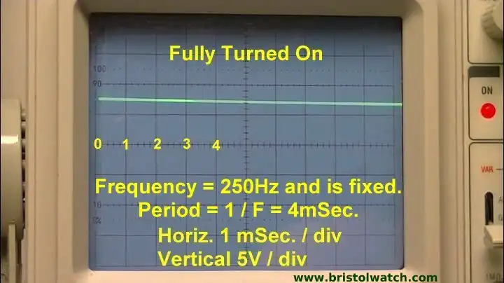
Fig. 6 Pulse width duty cycle 100 percent.
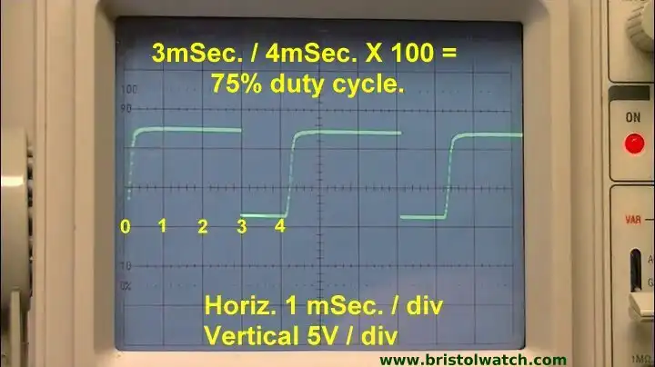
Fig. 7 Pulse width duty cycle 75 percent.

Fig. 8 Pulse width duty cycle 50 percent.
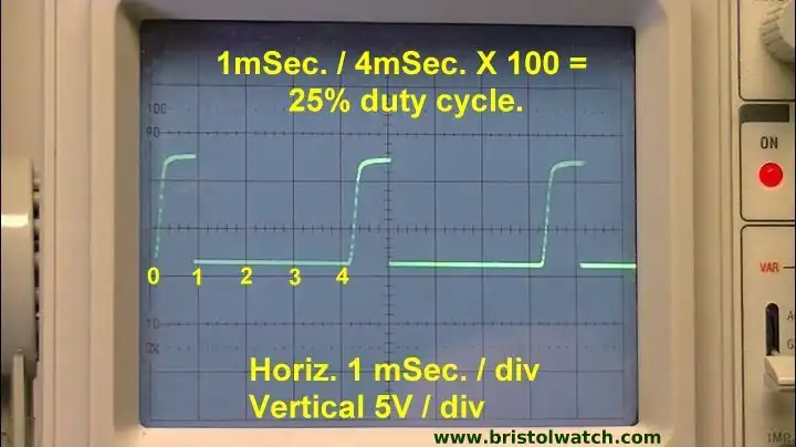
Fig. 9 Pulse width duty cycle 25 percent.
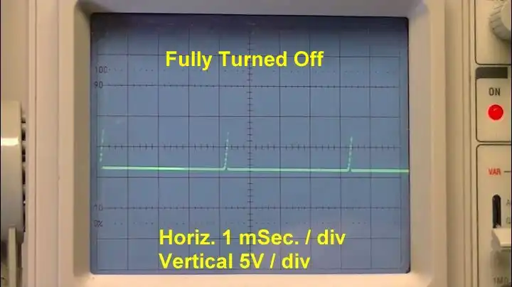
Fig. 10 Pulse width duty cycle 0 percent or off.
That ends this brief introduction to pulse-width modulation. Be sure to see my You Tube video.
![]()
- Quick navigation of this website:
- You Tube Channel
- Basic Electronics Learning and Projects
- Basic Solid State Component Projects
- Arduino Microcontroller Projects
- Raspberry Pi Electronics, Programming
- Operation switching power supplies and transformer connection tutorials:
- Generating High Voltage with an Inductor
- Arduino Buck Switching Voltage Regulator Demo Only
- Switching Regular Configuration Review
- LM2575 Simple Switching Voltage Regulators
- Voltage Buck-Boost Transformer Connections Tutorial
- Pulse Width Modulation Power Control
- AC Load Lamp Safely Allows Electronic Testing
- Build Autotransformer-Variac AC and DC Power Supply
- Connecting Transformers in Series-Parallel
- Build an Adjustable 0-34 volt power supply with the LM317
- AC Power Supply Rectification
- Basic Power Transformers
- Transistor-Zener Diode Regulator Circuits
- Tips for the LM78XX Series Voltage Regulators
- Bi-Polar Power Supplies
- Connecting Series-Parallel Batteries
Opto-Coupler SCR and Triac Circuits
SCRs and Triacs are used to control AC and DC power systems. With a microcontroller such as Arduino using a zero-crossing can control AC power to control light levels, AC motor speed, and resistive heating elements..
- Basic Triacs and SCRs
- Solid State AC Relays with Triacs
- Diac Waveform Generator, Trigger Circuits
- SIDAC Operation and Trigger Circuits
- Light Activated Silicon Controlled Rectifier (LASCR)
- Light Activated SCR Based Optocouplers Circuit Examples
- Comparing Photo Triac, Photo SCR Opto-Couplers
- Silicon Controlled Rectifier Review and Circuits
- Silicon Controlled Rectifiers Connected as Power Triacs
- Simple Triac-SCR Test Lab for You Tube
- AC Zero Crossing Detectors for Arduino
- Zero-Crossing Detectors Circuits
- Hardware Interrupts Demo and Tutorial for Arduino
- In Depth Look at AC Power Control with Arduino
- Arduino AC Power Control Using Interrupts
Web site Copyright Lewis Loflin, All rights reserved.
If using this material on another site, please provide a link back to my site.