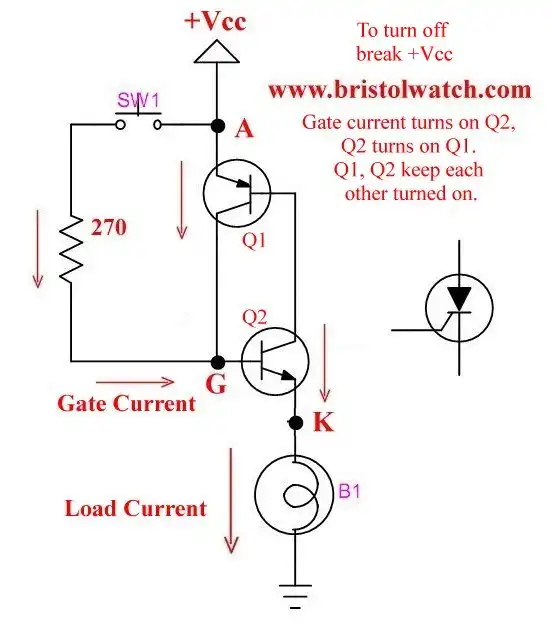
Fig. 1
Silicon Controlled Rectifier Review and Circuits
by Lewis Loflin
A silicon controlled rectifier sometimes called a Thyristor is simply a diode with a gate. They are used in a number of circuits usually AC-DC power control. They are related to Triacs that I won't cover here.
See Basic Triacs and Silicon Control Rectifiers.
In theory they can be represented as two transistors connected as shown in Fig. 1. When a small current flows between the gate and cathode the device will conduct and keep conducting until anode to cathode current flow is halted.
Referring to Fig. 1 when SW1 is pressed the small gate current, limited by a 270 Ohm resistor, turns on Q2. Then Q2 turns on Q1 and they keep each other turned on.
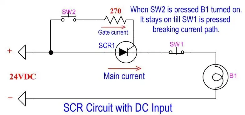
Fig. 2
In Fig 2 I have redrawn the circuit. Press SW2 the gate current turns on SCR1. Press SW1 (normally closed) the current path is broken the lamp turns of.
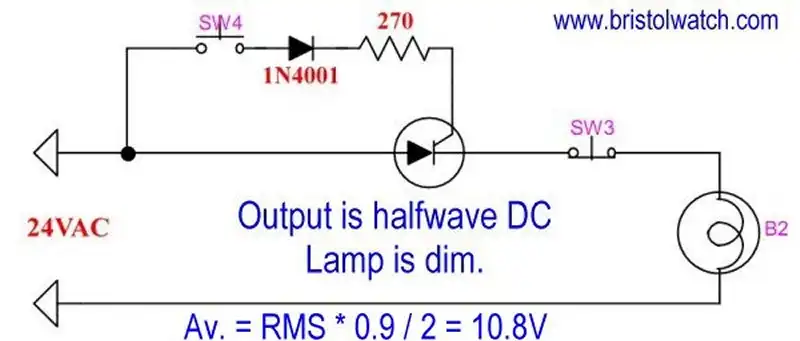
Fig. 3
In Fig. we input an AC voltage. Press SW4 the lamp comes on at half power. SCR1 acts merely as a halfwave rectifier. Release SW4 and the lamp turns off. When the AC cycles to zero SCR1 is turned off.
The diode is used to block the negative half-cycle from the SCR gate.
This property is useful when dealing with AC power control circuits. See Basic Power Supply Rectification Tutorial.
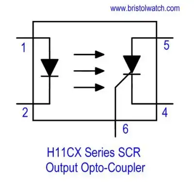
Fig. 4a
In Fig. 4a is an SCR based opto-coupler used to control higher power SCR circuits. This provides an interface between a PLC or low voltage microcontroller.
Update January 2025. The above type optocoupler is longer available. A triac based optocoupler such as the MOC3010, etc. with a diode can be substituted.
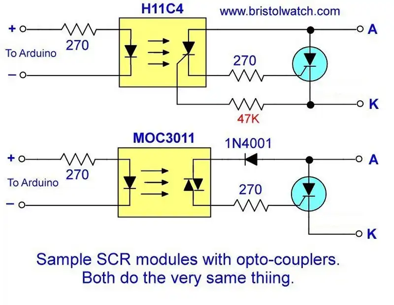
Fig. 4b Triac optocoupler with diode replaces SCR output optocoupler.
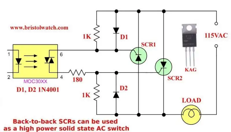
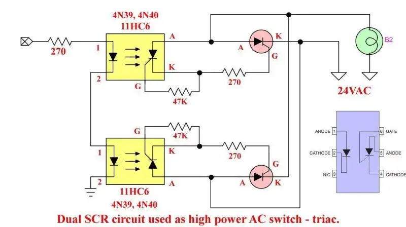
Fig. 4c Triac optocoupler used with dual SCRs to form a power triac.
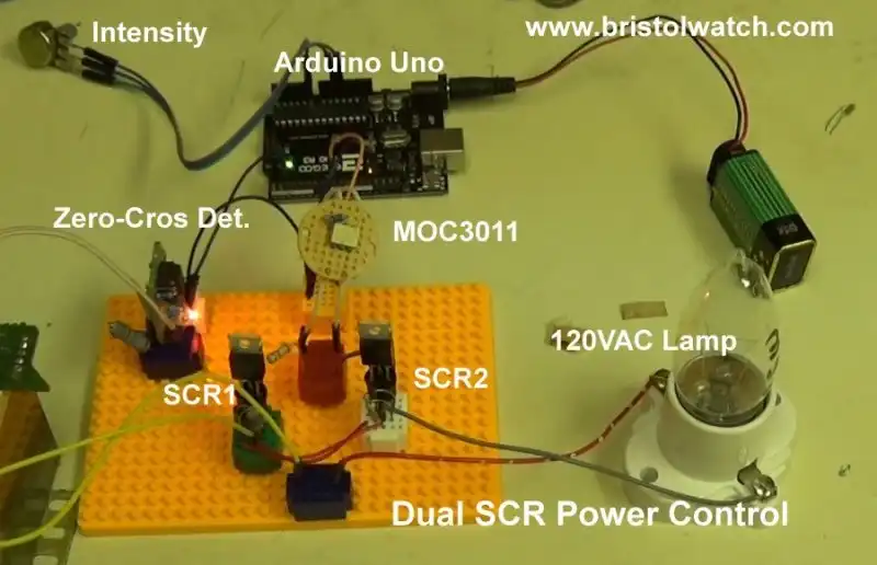
Fig. 5
For more on this see the following:
- Dual Silicon Controlled Rectifiers Connected as a Power Triac
- Light Activated Silicon Controlled Rectifier Based Optocouplers
- What is a Light Activated Silicon Controlled Rectifier? (LASCR)
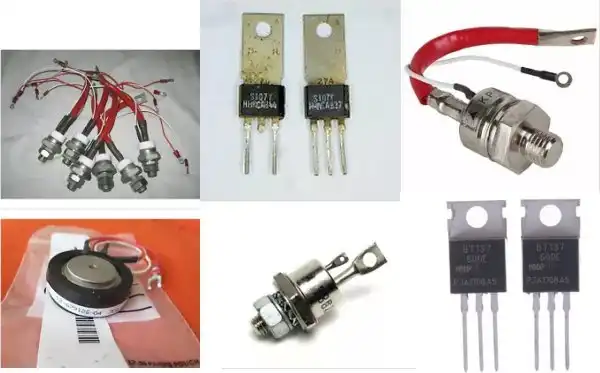
Fig. 6
Fig. 6 illustrates a few of the many case styles available. Some can carry hundreds of amps of current and are very expensive.
Another issue is gate sensitivity. Many high power SCRs require higher gate drive currents. Check you data sheet. The unit in the lower left corner I've seen used in industrial welding equipment.
Note this dual SCR circuit made from those separate opto-coupler SCR modules.
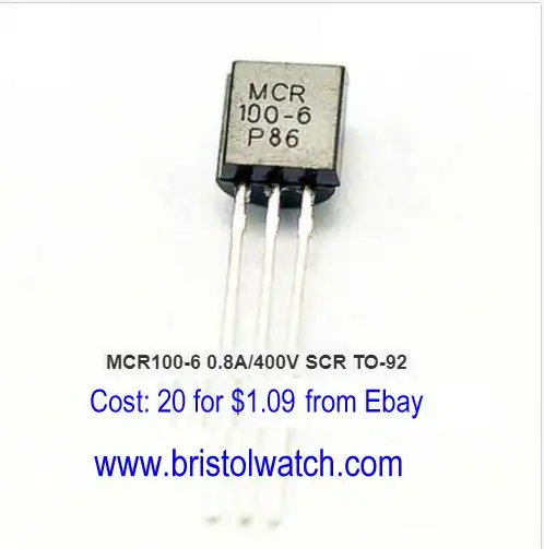
Fig. 8
Fig. 8 illustrates the MCR100-6 SCR rated at 800mA at 400 volts. I used these to build lower-power test circuits at 24 volts before moving over to the BT137-600 at 120 volts.
They can also be used to drive less sensitive, high power SCRs.
Both the BT148-600 (600V, 4A) and MCR100-6 SCRs I bought off of Ebay. Be careful when reading the Ebay pages because some vendors throw the term Triac around for SCRs and Thyristor around for Triacs. Check the part number data sheet before you buy!
- Exploring Solid State Relays and Control Circuits
- Comparing Photo Triac, Photo SCR Opto-Couplers
- Light Activated SCR Based Optocouplers Circuit Examples
- Silicon Controlled Rectifier Review and Circuits
- Silicon Controlled Rectifiers Connected as Power Triacs
- Insulated Gate Bipolar Transistor IGBT Circuits
- Current Limiter Circuits for Opto-Coupler LEDs
- VOM1271 Photovoltaic MOSFET Driver Circuits
- Current Limiter Allows Safe Testing of Zener Diodes, LEDs
- 3 Amp LM741 Op-Amp Constant Current Source
- Bidirectional Solid State Relay Circuits
- Simple Solid State Relay for Low Power LED 120V Lamps
- Build High Power MOSFET Directional Switch Relay
- Optical Isolation of H-Bridge Motor Controls
- All NPN Transistor H-Bridge Motor Control
- Basic Transistor Driver Circuits for Micro-Controllers
- ULN2003A Darlington Transistor Array with Circuit Examples
- Tutorial Using TIP120 and TIP125 Power Darlington Transistors
- Driving 2N3055-MJ2955 Power Transistors with Darlington Transistors
- Understanding Bipolar Transistor Switches
- N-Channel Power MOSFET Switching Tutorial
- P-Channel Power MOSFET Switch Tutorial
- Build a Transistor H-Bridge Motor Control
- H-Bridge Motor Control with Power MOSFETS
- More Power MOSFET H-Bridge Circuit Examples
- Build a High Power Transistor H-Bridge Motor Control
- H-Bridge Motor Control with Power MOSFETS Updated
- Opto-Isolated Transistor Drivers for Micro-Controllers
- Comparator Theory Circuits Tutorial
- Constant Current Circuits with the LM334
- LM334 CCS Circuits with Thermistors, Photocells
- LM317 Constant Current Source Circuits
- TA8050P H-Bridge Motor Control
- All NPN Transistor H-Bridge Motor Control
- Basic Triacs and SCRs
- Comparator Hysteresis and Schmitt Triggers
- Comparator Theory Circuits Tutorial
- Photodiode Circuits Operation and Uses
- Optocoupler MOSFET DC Relays Using Photovoltaic drivers
- Connecting Crydom MOSFET Solid State Relays
- Photodiode Op-Amp Circuits Tutorial
- Optocoupler Input Circuits for PLC
- H11L1, 6N137A, FED8183, TLP2662 Digital Output Optocouplers
- Optical Isolation of H-Bridge Motor Controls
- All NPN Transistor H-Bridge Motor Control
© Copyright 2019 Lewis Loflin E-Mail