Fig. 1
MOSFET based DC Relays Using Photovoltaic Drivers
by Lewis Loflin
Here we will explore the use of photovoltaic output opto-couplers. These are often used to drive power MOSFETs. These are based on the use of an array of photodiodes connected in series used to generate a gate drive voltage.
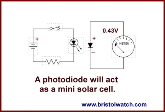
For more on basic photodiodes see For more on the basic operation see Photodiode Circuits Operation and Uses.
Let's look at an older circuits I've used in the past. Fig. 1 shows the use of a NPN transistor output opto-coupler to switch the turn-on voltage to the gate of Q1 a N-channel MOSFET.
The limitation of this type circuit is due to the collector-emitter breakdown voltage of the opto-coupler and the gate-source breakdown voltage (Vgs) on the MOSFET.
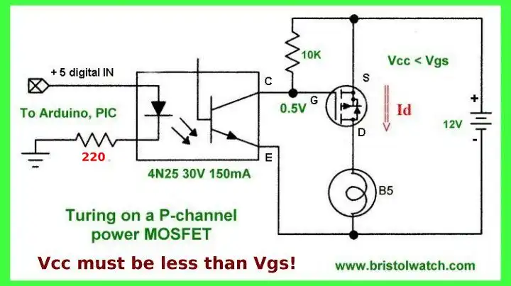
Fig. 2
Fig. 2 shows the P-channel variation of Fig. 1. The same problems exist here as well where voltage breakdown of the opto-coupler and Vgs limit the voltage to about 20 volts.
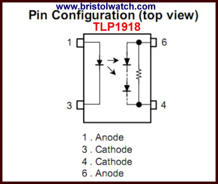
Fig. 3
Fig. 3 illustrates the internal connections to the TLP1918 photovoltaic output opto-coupler. This consists of a LED emitter and a series array of photodiodes to generate 7-10 volts output. This also includes an internal gate bleeder (assumes a MOSFET) resistor to shut off a MOSFET when the LED emitter is turned off.
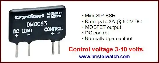
Fig. 4
Fig. 4 illustrates the PVI5050N series photovoltaic MOSFET drivers. These don't include an internal gate bleeder resistor which must be added externally.
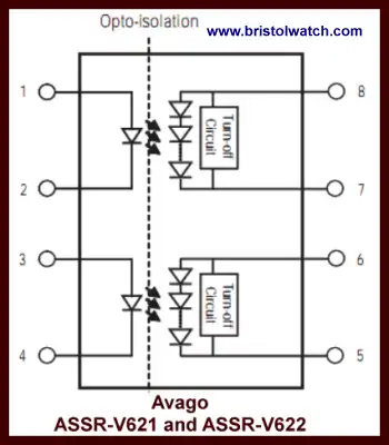
Fig. 5
Fig. 5 illustrates ASSR-V621 series photovoltaic output opto-couplers with internal gate turnoff circuit. These are dual drive devices oriented toward driving MOSFETs.
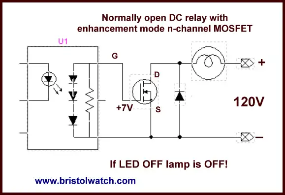
Fig. 6
Fig. 6 illustrates using an enhancement mode MOSFET with photovoltaic output opto-coupler. Unlike the earlier transistor based opto-couplers the problem of limitations due to C-E breakdown and Vgs is eliminated. We are limited only by the drain-source current and voltage ratings.
This creates a N.O. relay that is turned on when the LED emitter is turned on.
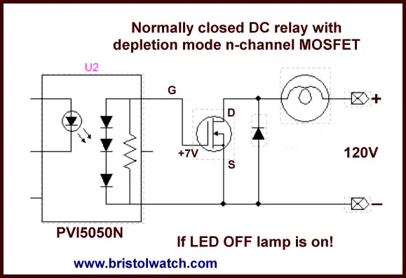
Fig. 7
Fig. 6 illustrates using an depletion mode MOSFET with photovoltaic output opto-coupler. Unlike the earlier transistor based opto-couplers the problem of limitations due to C-E breakdown and Vgs is eliminated. We are limited only by the drain-source current and voltage ratings.
This creates a N.C. relay that is turned off when the LED emitter is turned on.
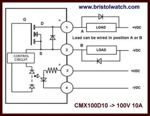
Fig. 8
The above ideas are used in commercial devices. This example device has a 3-32 volt input circuit and the load can be connected either way as shown in fig. 8.
- Quick navigation of this website:
- Basic Electronics Learning and Projects
- Basic Solid State Component Projects
- Arduino Microcontroller Projects
- Raspberry Pi Electronics, Programming
- Comparator Theory Circuits Tutorial
- Zero-Crossing Detectors Circuits and Applications
- Improved AC Zero Crossing Detectors for Arduino
- Photodiode Circuits Operation and Uses
- Photodiode Op-Amp Circuits Tutorial
- Issues on Connecting MOSFETs in Parallel
- MOSFET DC Relays Using Photovoltaic drivers
- Optocoupler Input Circuits for PLC
- All NPN Transistor H-Bridge Motor Control
- Photo Voltaic Tutorial MOSFET Output Solid State Relays
- Optical Isolation of H-Bridge Motor Controls
- Design 10-Amp 2N3055 Based Power Switch
- TA8050P H-Bridge Motor Control
- Connecting Crydom MOSFET Solid State Relays
- H11L1, 6N137A, FED8183, TLP2662 Digital Output Optocouplers
- Arduino
- Arduino PWM to Analog Conversion
- Arduino Analog Digital Conversion Voltmeter
- Better Arduino Rotary Encoder Sensor
- Simple 3-Wire MAX6675 Thermocouple ADC Arduino Interface
- Hall Effect Magnetic Switches and Sensors
- Transistor-Zener Diode Regulator Circuits
- Build an Adjustable 0-34 volt power supply with the LM317
- Coils for Highly Selective Crystal Radio
- Neon (NE-2) Circuits You Can Build
- Understanding Xenon Flashtubes and Circuits
- LM2575 Simple Switching Voltage Regulators
- Simple 2 Transistor LED Flasher Circuit
- Generating High Voltage with an Inductor
Web site Copyright Lewis Loflin, All rights reserved.
If using this material on another site, please provide a link back to my site.