Fig. 1
Arduino Pulse-Width Modulation Digital to Analog Conversion
by Lewis Loflin
Here we will discuss the operation of pulse-width-modulation to DC conversion and use the idea to construct a variable Arduino based DC power supply.
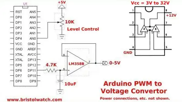
Fig. 1 illustrates using a LM358 in conjunction with a low-pass filter (10uF cap, 4.7K resistor) to produce a 0-5V output proportional to the duty cycle from DP11. The 10K potentiometer connected analog pin 0 is read, divided by 4, then written with analogWrite() to digital pin 11.
The reason we divided the ADC value by 4 is because the PWM as used with Arduino is 8-bit and not 10-bit. This same circuit works with a Microchip PIC as 10-bit with better resolution. The resolution is 5V / 255 = 19.61mV per step.
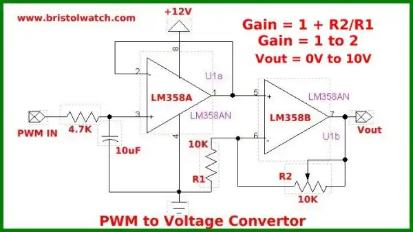
Fig. 2
Fig. 2 show using the other half of the LM358 as a voltage amplifier whose gain is based in 1 + R2/R1. With the 10K potentiometer connected between output pin 7 and fed back to the inverted input we can adjust for a gain of 1 to 2. The output with a 12-volt supply is 0-10V or 2-volts below Vcc.
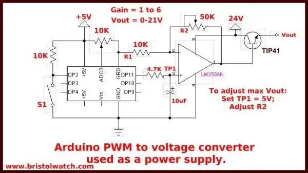
Fig. 3
In Fig. 3 we take the same circuit in Fig 2 but use a single LM358 as a voltage amplifier, boost Vcc to 24-volts, and change the 10K to 50K giving a gain of 1 to 6. We have also added a TIP41 NPN power transistor to boost output current.
First adjust the 10K pot on ADC0 for 5-volts at TP1, then adjust R2 for a maximum voltage out between 5 and 20-volts. While this is showing an Arduino NANO it will work with any Arduino.
Below is a sample program and if one wants to use an I2C LCD display that connection is illustrated below.
Out next project is to use the above in conjunction with a LM311 comparator to measure voltages up to 20-volts.
See Arduino Analog to Digital Conversion Voltmeter.
#include <Wire.h>
#include <LiquidCrystal_I2C.h>
// set the LCD address to 0x27
// 2-lines 16-char numbered 0-15
LiquidCrystal_I2C lcd(0x27,16,2);

int potValue;

void setup(void) {
  lcd.init(); // initialize the lcd
  lcd.backlight();
}

void loop(void) {

  potValue = analogRead(0) / 4 ;
  analogWrite(11, potValue);
  lcd.print("potValue =       ");
  lcd.setCursor(11,0);

  lcd.print(potValue);
  lcd.home();
  delay(200);
}
- Quick navigation of this website:
- Basic Electronics Learning and Projects
- Basic Solid State Component Projects
- Arduino Microcontroller Projects
- Raspberry Pi Electronics, Programming
- Comparator Theory Circuits Tutorial
- Zero-Crossing Detectors Circuits and Applications
- Improved AC Zero Crossing Detectors for Arduino
- Photodiode Circuits Operation and Uses
- Photodiode Op-Amp Circuits Tutorial
- Issues on Connecting MOSFETs in Parallel
- MOSFET DC Relays Using Photovoltaic drivers
- Optocoupler Input Circuits for PLC
- All NPN Transistor H-Bridge Motor Control
- Photo Voltaic Tutorial MOSFET Output Solid State Relays
- Optical Isolation of H-Bridge Motor Controls
- Design 10-Amp 2N3055 Based Power Switch
- TA8050P H-Bridge Motor Control
- Connecting Crydom MOSFET Solid State Relays
- H11L1, 6N137A, FED8183, TLP2662 Digital Output Optocouplers
Arduino
- Arduino
- Arduino PWM to Analog Conversion
- Arduino Analog Digital Conversion Voltmeter
- Better Arduino Rotary Encoder Sensor
- Simple 3-Wire MAX6675 Thermocouple ADC Arduino Interface
- Hall Effect Magnetic Switches and Sensors
- Transistor-Zener Diode Regulator Circuits
- Build an Adjustable 0-34 volt power supply with the LM317
- Coils for Highly Selective Crystal Radio
- Neon (NE-2) Circuits You Can Build
- Understanding Xenon Flashtubes and Circuits
- LM2575 Simple Switching Voltage Regulators
- Simple 2 Transistor LED Flasher Circuit
- Generating High Voltage with an Inductor
Web site Copyright Lewis Loflin, All rights reserved.
If using this material on another site, please provide a link back to my site.