Fig. 1
H11L1, 6N137A, FED8183, TLP2662 Digital Output Optocouplers
Here we explore digital output optocouplers. They all consists of a LED emitter but the output circuit often consists of a photodiode detector, an op-amp Schmitt trigger, comparator, or amplifier, and an open collector out transistor.
Besides voltage and noise isolation these are designed for high speed switching such as a engine controller in one's automobile or high speed controls for production machinery.
Applications include:
Microprocessor system interface
PLC, ATE input/output isolation
Computer peripheral interface
Digital fieldbus isolation: CC-link, DeviceNet, profibus, SDS
High speed A/D and D/A conversion
AC plasma display panel level shifting
Multiplexed data transmission
Digital control power supply
Ground loop elimination
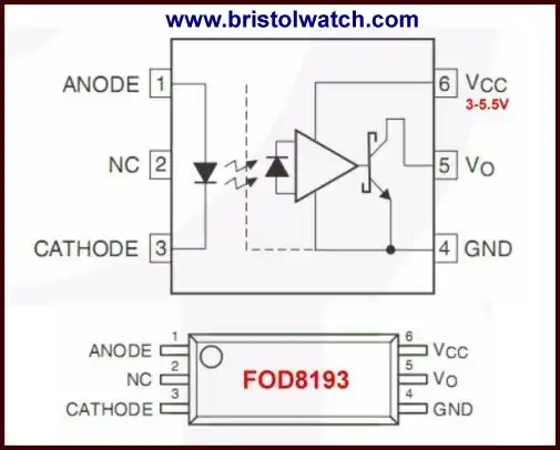
An excellent example is the FOD8193 with an open collector output. This is a surface mount device.
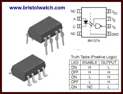
Fig. 2
The 6N137A is single channel 10 MBd optocouplers utilizing a high efficient input LED coupled to a very high speed integrated photo-detector logic gate with a strobable output. This detector features an open collector.
The internal shield provides a guaranteed common mode transient immunity of 1 kV/us. The use of a 0.1 uF bypass capacitor connected between pin 5 and 8 is recommended.
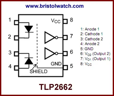
Fig. 3
The TLP2662/TLP2662F consists of high-intensity infrared light-emitting diodes (LEDs) optically coupled to a high-gain, high-speed photoreceptor chip. The TLP2662/TLP2662F guarantees operation at up to 125 degrees C and on supplies from 2.7 V to 5.5 V.
It is offered in the DIP8 package. With two LED-photoreceptor pairs, the TLP2662/TLP2662F helps save board space. An internal noise shield provides superior common-mode rejection for improved noise immunity.
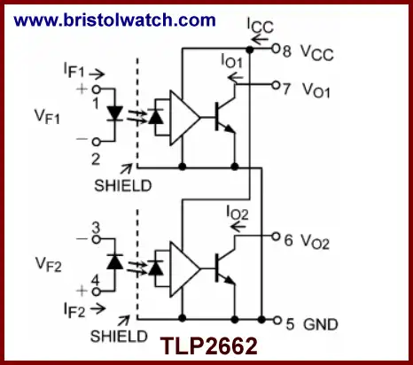
Fig. 4
Internal diagram of the TLP2662.
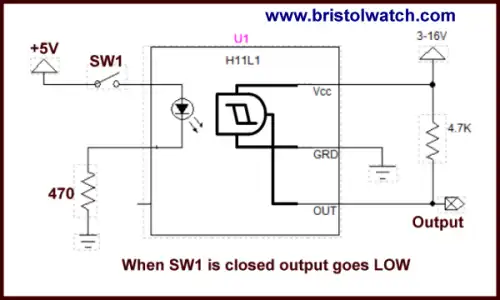
Fig. 5
The H11L1 and H11L2 have a gallium arsenide infra-red LED optically coupled to a high-speed integrated detector with Schmitt trigger output. Designed for applications requiring electrical isolation, fast response time, noise immunity and digital logic compatibility.
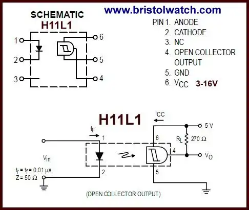
Fig. 6
Uses for the H11L1:
Interfacing Computer Terminals to Peripheral Equipment
Digital Control of Power Supplies
Line Receiver - Eliminates Noise
Digital Control of Motors and Other Servo Machine Applications
Logic to Logic Isolator
Logic Level Shifter - Couples TTL to CMOS
- Quick navigation of this website:
- Basic Electronics Learning and Projects
- Basic Solid State Component Projects
- Arduino Microcontroller Projects
- Raspberry Pi Electronics, Programming
- Comparator Theory Circuits Tutorial
- Zero-Crossing Detectors Circuits and Applications
- Improved AC Zero Crossing Detectors for Arduino
- Photodiode Circuits Operation and Uses
- Photodiode Op-Amp Circuits Tutorial
- Issues on Connecting MOSFETs in Parallel
- MOSFET DC Relays Using Photovoltaic drivers
- Optocoupler Input Circuits for PLC
- All NPN Transistor H-Bridge Motor Control
- Photo Voltaic Tutorial MOSFET Output Solid State Relays
- Optical Isolation of H-Bridge Motor Controls
- Design 10-Amp 2N3055 Based Power Switch
- TA8050P H-Bridge Motor Control
- Connecting Crydom MOSFET Solid State Relays
- H11L1, 6N137A, FED8183, TLP2662 Digital Output Optocouplers
- Arduino
- Arduino PWM to Analog Conversion
- Arduino Analog Digital Conversion Voltmeter
- Better Arduino Rotary Encoder Sensor
- Simple 3-Wire MAX6675 Thermocouple ADC Arduino Interface
- Hall Effect Magnetic Switches and Sensors
- Transistor-Zener Diode Regulator Circuits
- Build an Adjustable 0-34 volt power supply with the LM317
- Coils for Highly Selective Crystal Radio
- Neon (NE-2) Circuits You Can Build
- Understanding Xenon Flashtubes and Circuits
- LM2575 Simple Switching Voltage Regulators
- Simple 2 Transistor LED Flasher Circuit
- Generating High Voltage with an Inductor
Web site Copyright Lewis Loflin, All rights reserved.
If using this material on another site, please provide a link back to my site.