Fig. 1
Insulated Gate Bipolar Transistor IGBT Circuits Tutorial
by Lewis Loflin
Also see IGBT Based High Voltage H-Bridge DC Motor Control.
Recently I discovered the advantages of using Insulated Gate Bipolar Transistors (IGBTs) over MOSFETs. In fact I had several left over from my plasma cutter repair days and decided to use them. This is particularly true when used with photovoltaic MOSFET drive opto-couplers such as the VOM1271.
See VOM1271 Photovoltaic MOSFET Driver Circuits.
To quote two sources on the advantages of IGBTs:
When compared to the IGBT, a power MOSFET has the advantages of higher commutation speed and greater efficiency during operation at low voltages. ... The IGBT combines the simple gate-drive characteristics found in the MOSFET with the high-current and low-saturation-voltage capability of a bipolar transistor.
And:
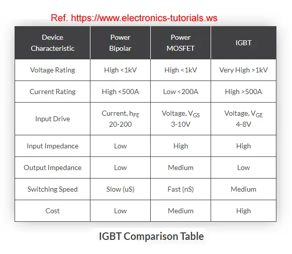
The main advantages of using the Insulated Gate Bipolar Transistor over other types of transistor devices are its high voltage capability, low ON-resistance, ease of drive, relatively fast switching speeds and combined with zero gate drive current makes it a good choice for moderate speed, high voltage applications...
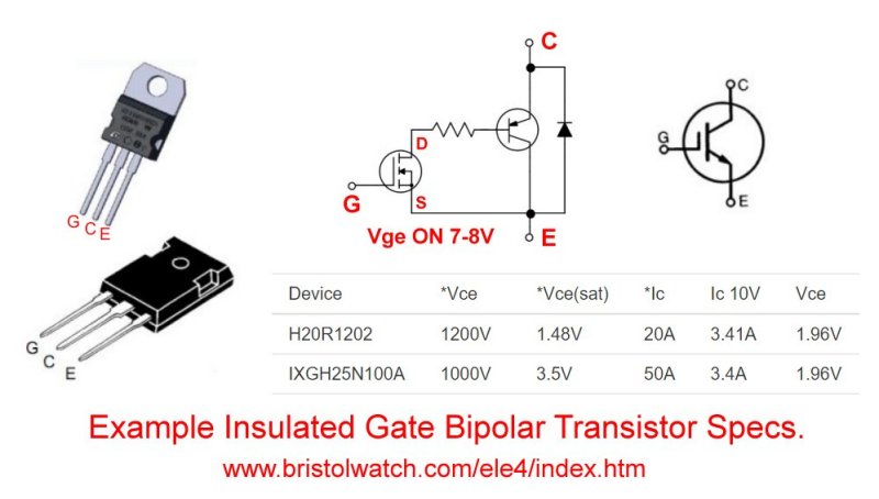
Fig. 1 Basic theory behind IGBT construction as N-channel MOSFET and PNP transistor.
www.designnews.com (July 14, 2021) calls IGBTs "One of the Most Power Efficient Devices Around". To quote,
One key example of the latter is the Insulated-gate bipolar transistor or IGBT, a three-terminal power semiconductor device primarily used as an electronic switch. Since it is designed to turn on and off rapidly, IGBT’s are widely used as switching devices in inverter DC-to-DC circuits for driving small to large motors...
According to Mordor Intelligence, the IGBT market was valued at USD 6.047 billion in 2020, and it is expected to reach USD 11.01 billion by 2026. The report notes that IGBT controls electrical energy via switching amplifiers in several modern appliances, such as cookers, microwaves, electric cars, trains, variable-frequency drives (VFDs), refrigerators, air conditioners, lamps ballasts, municipal power transmission systems, and stereo systems.
Another reason for the growth of IGBTs is the electrification of the automotive power trains in electric and hybrid vehicles (EV/HEV). With IGBTs, conduction and switching losses are significantly reduced, thus directly impacting the vehicle's overall efficiency.
They note IGBTs are replacing older Gate Turn Off Thyristors (GTOs) in locomotive motors. Yes trains use electric motors. IGBTs can be used in compact fluorescent lamps, etc. to increase efficiency.
New York, Aug. 03, 2020 (GLOBE NEWSWIRE) reports:
IGBT is critical to electrical and electronic system and deemed as the ‘CPU’ of the electrical and electronic industry.
IGBT is given full play under varied voltage class, like its exertion under 650~1200V in electric vehicle, 650V in home appliances and industrial fixing, either 650V or 1200V in new energy vehicle, and above 1700V in PV, industrial motors, high-speed railway, bullet trains, smart grid, etc.
Power semiconductors are exponentially utilized as automotive technologies are transferring to focus on new energy vehicle...IGBT module serving as high-voltage control switch component constitutes about 40% of motor controller costs. IGBT devices make up about 10% of new cost and share roughly 20% of charging pile costs.
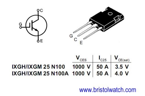
Fig. 2a
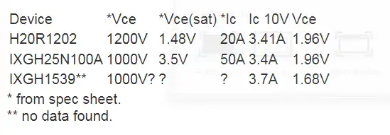
The IXGH25N100 are the ones I used in my test circuits. Mine were salvaged from a plasma cutter inverter board I'll discuss below.
Besides the high voltage capability some have a "maximum rated collector current Ic(max) exceeding 100A".
The symbol for an IGBT is on the left.
The IXGH25N100 does not have internal flywheel diodes.
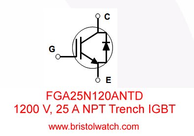
Fig. 2b
Fig. 2b illustrates an IGBT with internal flywheel diodes. The FGA25N120 is rated at 1200V, 25A. Voltage C-E sat at 25A is 2.0V.
An important factor is collect-emitter saturation voltage. The following are used in inductive heating circuits.
FGPF4633 is rated 330V a V C-E 1.55V at 70A.
IHW20N120R3 1200V 20A 1.48V.
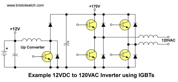
Fig. 3
Example 12VDC to 120VAC IGBT inverter circuit.
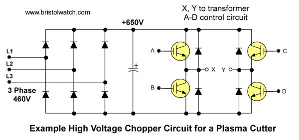
Fig. 4
Inverter plasma cutters
I used to repair portable plasma cutters of this type. To quote Wikipedia:
Inverter plasma cutters rectify the mains supply to DC, which is fed into a high-frequency transistor inverter between 10 kHz to about 200 kHz. Higher switching frequencies allow smaller transformer resulting in overall size and weight reduction.
The transistors used were initially MOSFETs, but are now increasingly using IGBTs. With paralleled MOSFETs, if one of the transistors activates prematurely it can lead to a cascading failure of one quarter of the inverter. A later invention, IGBTs, are not as subject to this failure mode. IGBTs can be generally found in high current machines where it is not possible to parallel sufficient MOSFET transistors.
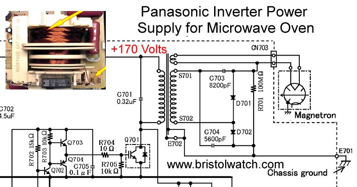
Fig. 5
Fig. 5 uses an IGBT to chop 170v DC for high frequency transformer. This is used in Panasonic microwave ovens.
The higher frequency allows use of smaller (cheaper) transformers. This also reduces weight. D701, D701, C703, and C704 form a voltage doubler. R701 is a HV bleeder resistor.
Because I could use the same test setup for IGBTs as n-channel MOSFETs I tested those I had.
IGBTs at least those I own shouldn't be used unless it's a very high voltage circuit. They have a high voltage drop (Vce ~2V) with low voltage h-bridge circuits and are better used for higher voltage switching.
See Test Power MOSFET Transistors, IGBTs Results, Observations
Conclusion: IGBTs don't work directly with 3.3V and 5V micro-controllers such as Arduino. At least 7-volts is required for turn on. The high Vce of 1.5V to 2V can waste power.
IGBTs do differ from MOSFETs with both positive flow and electron flow could deliver more power even at 2V Vce to the load. They are really designed for high-voltage switching.
- Exploring Solid State Relays and Control Circuits
- Comparing Photo Triac, Photo SCR Opto-Couplers
- Light Activated SCR Based Optocouplers Circuit Examples
- Silicon Controlled Rectifier Review and Circuits
- Silicon Controlled Rectifiers Connected as Power Triacs
- Insulated Gate Bipolar Transistor IGBT Circuits
- Current Limiter Circuits for Opto-Coupler LEDs
- VOM1271 Photovoltaic MOSFET Driver Circuits
- Current Limiter Allows Safe Testing of Zener Diodes, LEDs
- 3 Amp LM741 Op-Amp Constant Current Source
- Bidirectional Solid State Relay Circuits
- Simple Solid State Relay for Low Power LED 120V Lamps
- Build High Power MOSFET Directional Switch Relay
- Optical Isolation of H-Bridge Motor Controls
- All NPN Transistor H-Bridge Motor Control
- Basic Transistor Driver Circuits for Micro-Controllers
- ULN2003A Darlington Transistor Array with Circuit Examples
- Tutorial Using TIP120 and TIP125 Power Darlington Transistors
- Driving 2N3055-MJ2955 Power Transistors with Darlington Transistors
- Understanding Bipolar Transistor Switches
- N-Channel Power MOSFET Switching Tutorial
- P-Channel Power MOSFET Switch Tutorial
- Build a Transistor H-Bridge Motor Control
- H-Bridge Motor Control with Power MOSFETS
- More Power MOSFET H-Bridge Circuit Examples
- Build a High Power Transistor H-Bridge Motor Control
- H-Bridge Motor Control with Power MOSFETS Updated
- Opto-Isolated Transistor Drivers for Micro-Controllers
- Comparator Theory Circuits Tutorial
- Constant Current Circuits with the LM334
- LM334 CCS Circuits with Thermistors, Photocells
- LM317 Constant Current Source Circuits
- TA8050P H-Bridge Motor Control
- All NPN Transistor H-Bridge Motor Control
- Basic Triacs and SCRs
- Comparator Hysteresis and Schmitt Triggers
- Comparator Theory Circuits Tutorial
- Photodiode Circuits Operation and Uses
- Optocoupler MOSFET DC Relays Using Photovoltaic drivers
- Connecting Crydom MOSFET Solid State Relays
- Photodiode Op-Amp Circuits Tutorial
- Optocoupler Input Circuits for PLC
- H11L1, 6N137A, FED8183, TLP2662 Digital Output Optocouplers
- Optical Isolation of H-Bridge Motor Controls
- All NPN Transistor H-Bridge Motor Control
© Copyright 2019 Lewis Loflin E-Mail