Figure 1
Hardware Interrupts Demo-Tutorial for Arduino
Here we will explore hardware interrupts on the Arduino microcontroller. This is an electrical signal change on a microcontroller pin that causes the CPU to do the following largely in this order:
1. Finish execution of current instruction.
2. Block any further interrupts.
3. The CPU will "push" the program counter onto a "stack" or memory storage location for later retrieval.
4. The program jump to an specific memory location (interrupt vector) which is an indirect pointer to a subroutine or function.
5. The CPU loads that memory address and executes the function or subroutine that should end with a "return" instruction.
6. The CPU will "pop" the original memory address from the "stack", load it into program counter, and continue execution of original program from where the interrupt occurred.
7. Will re-enable interrupts.
The advantage of hardware interrupts is the CPU doesn't waste most of its time "polling" or constantly checking the status of an IO pin.
Typical microcontrollers such as Arduino or PIC have a number of interrupt sources most of them tied into internal hardware modules such as timers and comparators, while some are tied into external hardware pins. This is programmed by setting or clearing bits in internal registers.
In the case of Arduino this is set by both the boot loader and the compiled program - access by the user is limited unless one wants to get into assembly programming. There are four available functions for controlling interrupts with Arduino: attachInterrupt(), detachInterrupt(), interrupts(), and noInterrupts(). We shall explore all four functions.
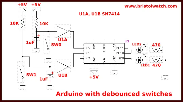
Most Arduino boards have two external interrupts: INTR0 (on DP2) and INTR1 (DP3). The Arduino Mega has an additional four INTR2-INTR5. Here we are interested in the INTR0 and INTR1.
Figure 1 shows the rest setup we will be using. SW0 through the "debounce" circuit formed by a SN7414 and a 1uF cap controls DP2 (INTR0) while SW1 corresponds to DP3. (INTR1) The switches are "debounced" to eliminate electrical contact noise that cause erratic operation. In all of the programming examples SW0 control an LED on DP9 and SW1 controls an LED on DP10.
When SW0 or SW1 is open a LOW or 0V is on the corresponding Arduino pin. When closed the pin goes HIGH or electrical 5V. A "0" or "1" to the compiler is understood as LOW or HIGH respectively. Same is true of FALSE and TRUE in comparison operations.
Our First Program
#define LED 9
volatile byte state = LOW;

void setup() {
  pinMode(LED, OUTPUT);
  attachInterrupt(0, toggle, RISING);
}

void loop() {
  digitalWrite(LED, state);
}

void toggle() {
  state = !state;
}
Above is our first sample program. The label "LED" to the compiler is defined as the number 9. So digitalWrite(LED, HIGH) is the same as digitalWrite(9, HIGH) which is the same as digitalWrite(LED, 1), etc.
The second line defines the variable "state" as both a byte (8-bit variable) and "volatile". This differs from the usual byte, integer, or float in how the system and compiler use it. If being used as an interrupt routine variable be it byte, float, etc. is must have a "volatile" declaration. The variable is set to 0 - in reality we are using only one of the eight bits, bit 0.
In setup() we come to the function attachInterrupt(interrupt, function, mode) where "interrupt" is the interrupt number 0 to 5; "function" is known as the interrupt service routine or ISR a function address pointed to by the interrupt vector location; "mode" configures the hardware electrical characteristics for an interrupt. This is done internally by the compiler and hidden from the user.
So in this case of attachInterrupt(0, toggle, FALLING) zero corresponds to interrupt 0 on DP2, toggle() is the ISR routine at the bottom of the program, and RISING means when an electrical signal goes from 0V to 5V the toggle() ISR performs its function - what started as state = LOW is now state = HIGH and vise-versa. The right "}" is considered the "return" command - in fact "return;" passed after "state = !state;" is ignored and won't produce an error.
In other words loop() will simply keep writing the variable "state" to the LED on DP9, and on an interrupt caused by pressing SW0 will halt, save address counter, jump to ISR toggle(), will come back where it stopped and continue.
Assuming the LED1 is off press SW0 and the LED will come on, release nothing happens. Press again and the LED is off. What toggle() really does is a bitwise XOR of 1; state = !state is the same as state = state ^ 1.
With attachInterrupt(interrupt, function, mode) there are four "mode" declarations that defines when the interrupt should be triggered and are predefined as:
RISING to trigger when the pin goes from low to high - as wired above press switch and LED state will toggle.
FALLING for when the pin goes from high to low - press switch nothing, release switch LED state will toggle.
CHANGE to trigger the interrupt whenever the pin changes value - press switch LED state will toggle, release switch LED will toggle again.
LOW to trigger the interrupt whenever the pin is low - sort of like FALLING but erratic - don't use.
Program Example 2
#define LED1 9
#define LED2 10
#define SW1 2
#define SW2 3

void toggle(byte pinNum) {
  byte pinState = !digitalRead(pinNum);
  digitalWrite(pinNum, pinState);
}

void setup()  {
  pinMode(LED1, OUTPUT);
  pinMode(LED2, OUTPUT);
  digitalWrite(LED1, 0); // LED off
  digitalWrite(LED2, 0); // LED off
  pinMode(SW1, INPUT);
  pinMode(SW2, INPUT);
  attachInterrupt(0, ISR0, FALLING);
  // interrupt 0 digital pin 2 connected SW0
  attachInterrupt(1, ISR1, RISING);
  // interrupt 1 digital pin 3 connected SW1
}

void loop() {
  // do nothing
}

// can't use delay(x) in IRQ routine
void ISR0() {
  toggle(LED1);
}

void ISR1() {
  toggle(LED2);
}
The above program introduces several new concepts. There are no "volatile" variables defined or needed. Both INTR0 (DP2) and INTR1 (DP3) both have their own separate ISR routines ISR0() and ISR1() respectively. There is a separate non-interrupt subroutine toggle().
In this case either ISR routines will simply call toggle() and will let toggle() do the work.
Certain functions such as delay() won't work inside a ISR function so it's a good idea to use separate subroutines as long as they are not overly complex or time consuming - another interrupt rolling onto an ISR called subroutine that hasn't finished could be interesting.
In addition functions that use interrupts such as delay() will not work if called from an ISR routine. For example the modified version of toggle() that follows won't work if called by an ISR but works fine if called from loop() or another non-interrupt subroutine. The selected LED will come on for two seconds then go off.
The ISR routine maintains control of the interrupts until it's finished and executes a "return" from interrupt command.
void toggle(byte pinNum) {
  byte pinState = !digitalRead(pinNum);
  digitalWrite(pinNum, pinState);
  delay(2000);
  pinState = pinState ^ 1;
  digitalWrite(pinNum, pinState);
} // last brace is understood as return.
The real solution is not to use the Arduino delay() function but write your own. the delayMicroceconds() doesn't require the use of interrupts but is limited to about 16,000 - 1000uSec. = 1mSec.; 1,000,000uSec. - 1 Sec. Simply use a for loop:
void myDelay(int x)   {
  for(int i=0; i<=x; i++)
  {
    delayMicroseconds(1000);
  }
}
Use myDelay(5000) for delay(5000) and the program will work.
Sample Program 3
// LED must be connected between
// digital pin and ground
#define LED1 9
#define LED2 10
#define SW1 2
#define SW2 3

// change state of an output pin
void toggle(byte pinNum) {
  byte pinState = !digitalRead(pinNum);
  digitalWrite(pinNum, pinState);
}

void setup()  {
  pinMode(LED1, OUTPUT);
  pinMode(LED2, OUTPUT);
  digitalWrite(LED1, 0); // LED off
  digitalWrite(LED2, 0); // LED off
  pinMode(SW1, INPUT);
  pinMode(SW2, INPUT);
  attachInterrupt(0, ISR0, FALLING);
  // interrupt 0 digital pin 2 connected SW0
  attachInterrupt(1, ISR1, RISING);
  // interrupt 1 digital pin 3 connected SW1
}

void loop() {
} // end loop

void myDelay(int x)   {
  for(int i=0; i<=x; i++)
  {
    delayMicroseconds(1000);
  }
}

void ISR0()
{
  toggle(LED1);
}

void ISR1(){
  detachInterrupt(0); // not needed!
  toggle(LED2);
  myDelay(5000); // 5 sec.
  toggle(LED2);
  attachInterrupt(0, ISR0, RISING); // not needed
  flag1 = 0; // clear flag
}
In the above sketch press SW0 and LED1 will toggle. Press SW1 and LED2 will turn on for 5 seconds at the same time ISR1 disconnects INTR0. Press SW1 during this time and when the 5 seconds are up LED1 will then toggle. If SW0 is pressed more than once during that 5 seconds only one will be remembered because flag0 will be interpreted as HIGH only once even if the count is greater than 1.
Final Example
#define LED1 9
#define LED2 10
#define SW1 2
#define SW2 3
volatile byte flag0 = LOW; // declare IRQ flag
volatile byte flag1 = LOW; // declare IRQ flag

// change state of an output pin
void toggle(byte pinNum) {
  byte pinState = !digitalRead(pinNum);
  digitalWrite(pinNum, pinState);
}

void setup()  {
  pinMode(LED1, OUTPUT);
  pinMode(LED2, OUTPUT);
  digitalWrite(LED1, 0); // LED off
  digitalWrite(LED2, 0); // LED off
  pinMode(SW1, INPUT);
  pinMode(SW2, INPUT);
  attachInterrupt(0, ISR0, FALLING);
  attachInterrupt(1, ISR1, RISING);
}

void loop() {
  noInterrupts();
  toggle(LED2);
  myDelay(2000);
  toggle(LED2);
  myDelay(2000);
  interrupts();
   // no other interrupt work except from here to begin loop.
} // end loop

void myDelay(int x)   {
  for(unsigned int i=0; i<=x; i++)
  {
    delayMicroseconds(1000);
  }
}

void ISR0()
{
  toggle(LED1);
}

void ISR1(){
  toggle(LED2);
  myDelay(5000); // 5 sec.
  toggle(LED2);
  flag1 = 0; // clear flag
}
Your turn to test this sketch.
That completes this introduction to Arduino interrupts.
- Quick navigation of this website:
- Basic Electronics Learning and Projects
- Basic Solid State Component Projects
- Arduino Microcontroller Projects
- Raspberry Pi Electronics, Programming
- For related:
- Basic Triacs and SCRs
- Solid State AC Relays with Triacs
- AC Zero Crossing Detectors for Arduino
- Zero-Crossing Detectors Circuits
- Arduino Controlled IR2110 Based H-Bridge HV Motor Control
- Arduino Measures Current from Constant Current Source
- Arduino Power Magnetic Driver Board for Stepper Motors
- Arduino Controlled Power Constant Current Source
- Arduino
- Arduino Power Inverter DC-AC Power Circuits
- Arduino PWM to Analog Conversion
- Arduino Analog Digital Conversion Voltmeter
- Rotary Encoder Using Arduino Hardware Interrupts
- Better Arduino Rotary Encoder Sensor
- Simple 3-Wire MAX6675 Thermocouple ADC Arduino Interface
- Arduino Stepper Motor Drive Coil Winder
- PCA9555 32-Bit GPIO Expander with Arduino
- PCA9555 GPIO Arduino, 4X4 Keypad
- PCA9555 GPIO Arduino Using Interrupts
- PCA9555 GPIO, Arduino, LCD Display
- Arduino IF Statement Code Examples
- Arduino LCD Display, 74164 Shift Register
- Programming ADS1115 4-Channel I2C ADC with Arduino
- Arduino uses ADS1115 with TMP37 to Measure Temperature
- Arduino with MCP4725 12-bit DAC Demo
Web site Copyright Lewis Loflin, All rights reserved.
If using this material on another site, please provide a link back to my site.