Programming ADS1115 4-Channel I2C ADC with Arduino
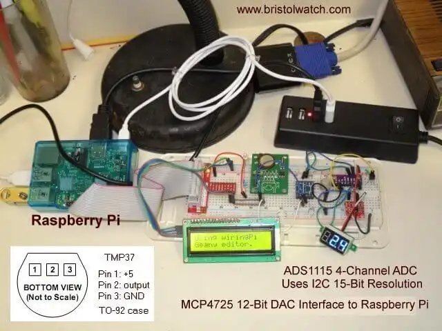
This project will read the voltage from a potentiometer connected to input A1 convert this to a voltage and display the value on the Arduino serial monitor. The ADS1115 consist of four inputs labeled A0-A3 all 15-bit resolution. Besides single ended ADC functions a number of comparator functions are also possible. For more on the functions-programming of the ADS1115 see the following:
ADS1115 4-Channel ADC Uses I2C with Raspberry Pi
Also ads1115.pdf spec sheet.
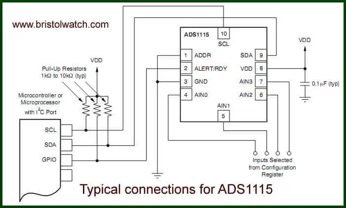
Electrical connections ADS1115.
Arduino sketch for this project: ads1115_demo.ino This explains the ADS1115 registers:
/ ASD1115
// set config register and start conversion
// ANC1 and GND, 4.096v, 128s/s
writeBuf[0] = 1;    // config register is 1
writeBuf[1] = 0b11010010; // 0xC2 single shot off
// bit 15 flag bit for single shot
// Bits 14-12 input selection:
// 100 ANC0; 101 ANC1; 110 ANC2; 111 ANC3
// Bits 11-9 Amp gain. Default to 010 here 001 P19
// Bit 8 Operational mode of the ADS1115.
// 0 : Continuous conversion mode
// 1 : Power-down single-shot mode (default)

writeBuf[2] = 0b10000101; // bits 7-0  0x85
// Bits 7-5 data rate default to 100 for 128SPS
// Bits 4-0  comparator functions see spec sheet.

// setup ADS1115
Wire.beginTransmission(ASD1115);  // ADC
Wire.write(writeBuf[0]);
Wire.write(writeBuf[1]);
Wire.write(writeBuf[2]);
Wire.endTransmission();
To configure the ADS1115 we use three bytes with the first being a register pointer. 1 is for the 16-bit configuration register and 0 for the 16-bit data register. Various bit settings are shown above - refer to the specification sheet for additional functions.
We write three bytes to the device. The first byte is a pointer to the configuration register where the next two bytes are written.
Here is the main section within loop:
const float VPS = 4.096 / 32768.0; // volts per step

buffer[0] = 0; // pointer
Wire.beginTransmission(ASD1115);  // DAC
Wire.write(buffer[0]);  // pointer
Wire.endTransmission();

Wire.requestFrom(ASD1115, 2);
buffer[1] = Wire.read();  //
buffer[2] = Wire.read();  //
Wire.endTransmission();

// convert display results
val = buffer[1] << 8 | buffer[2];

if (val > 32768) val = 0;

Serial.println(val * VPS);
Serial.println(val);
The first line is a constant VPS or volt-per-step. While we do have 16-bits bit D15 is used as a sign bit in other function so we have for this single-ended ADC 14-bit or 2^15 = 32,768 and divide this into 4.098-volts we defined in the configuration register.
The resolution is 125 uV per step. Compare this to an Arduino ADC input at 5v and 1024 steps is a resolution of 4.88 mV per step. That's a difference of 39 times the resolution.
The above demonstrated the continuous mode which was set by a bit 8 (this is 16-bits configured as two bytes) with writeBuf[1] = 0b11010010. If bit 8 was 1 would be in the single shot mode.
The ADS1115 defaults to this mode on power up when the internal electronics are in low-power sleep mode. Note that the configuration register is read-write while the data register is read only. When using this mode write to the registers are before, delay, then read the data register. It does one conversion then read the date register.
For every conversion one must again write the configuration register.
 do   {

    buffer[0] = 1; // pointer
    Wire.beginTransmission(ASD1115);  // DAC
    Wire.write(buffer[0]);  // pointer
    Wire.endTransmission();

    Wire.requestFrom(ASD1115, 2);
    buffer[1] = Wire.read();  //
    buffer[2] = Wire.read();  //
    Wire.endTransmission();

  }  while ((buffer[1] & 0x80) == 0);
Above we use a Do loop to using a bitwise AND checking bit D7 of buffer[1] testing for a HIGH or 1 before we read the data register. Note i didn't test this code but it should work.
Have fun. For earlier Arduino Projects see Arduino Projects Hobby Projects Tutorials
- Arduino IF Statement Code Examples
- Arduino Solid State Relay Motor Enable Control
- Arduino XOR Blinks LED
- Arduino Projects Revisited Revised
- Programming ADS1115 4-Channel I2C ADC with Arduino
- Arduino uses ADS1115 with TMP37 to Measure Temperature
- Connect Arduino to I2C Liquid Crystal Display
- Arduino Reads Temperature Sensor Displays Temperature on LCD Display
- Arduino with MCP4725 12-bit Digital-to-Analog Converter Demo
- Videos
- Arduino with ADS1115 4-Channel 16-bit Analog-to-Digital Converter
- Arduino with MCP4725 12-Bit DAC
- Using Zero-Crossing Detectors with Arduino
- Hardware Interrupts Demo and Tutorial for Arduino
- In Depth Look at AC Power Control with Arduino
- Micro-controller AC Power Control Using Interrupts
- Light Activated SCR Based Optocouplers Circuit Examples
- Solid State AC Relays with Triacs
- YouTube
- Zero-Crossing Detectors Circuits and Applications
- Zero-Crossing Circuits for AC Power Control
- In Depth Look at AC Power Control with Arduino
- Micro-controller AC Power Control Using Interrupts
- YouTube Video for Arduino AC Power Control
- Arduino
- Arduino PWM to Analog Conversion
- Arduino Analog Digital Conversion Voltmeter
- Better Arduino Rotary Encoder Sensor
- Simple 3-Wire MAX6675 Thermocouple ADC Arduino Interface
- YouTube:
- 3-Wire MAX6675 Thermocouple ADC Arduino Interface
- Arduino ADC Voltmeter YouTube video
- Arduino PWM to ADC YouTube video
- Arduino Nano Test Template
- Arduino Solid State Relay Motor Enable Control
- Arduino Blink LED Tutorial
- Arduino SSR Power Enable Program
- SSR Based High Voltage H-Bridge
- Arduino H-Bridge Motor Control Program with LCD Display
- Arduino XOR Blinks LED
- Arduino Motor Control Program Using IF
- ULN2003A Darlington Transistor Array with Circuit Examples
- Tutorial Using TIP120 and TIP125 Power Darlington Transistors
- Driving 2N3055-MJ2955 Power Transistors with Darlington Transistors
- Understanding Bipolar Transistor Switches
- N-Channel Power MOSFET Switching Tutorial
- P-Channel Power MOSFET Switch Tutorial
- H-Bridge Motor Control with Power MOSFETS
- More Power MOSFET H-Bridge Circuit Examples
- Build a High Power Transistor H-Bridge Motor Control