
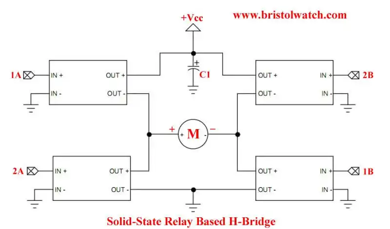
SSR Based High Voltage H-Bridge
by Lewis Loflin
See related Arduino Solid State Relay Motor Control.
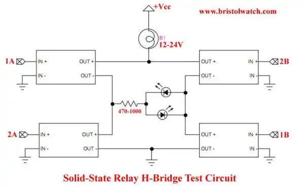
To use the above H-bridge circuit power on 1B and 1b at the same time. Make sure 2A and 2B are turned off. Connect 1A-1B to Arduino DP9. Connect 2A-2B to DP10.
To reverse direction turn off DP9 then turn on DP10.
Only when the above is wired and programmed correctly - polarity reverses and the lamp stays off, move to next step.
Using the program below motor should forward and reverse by pressing SW1 and SW2.
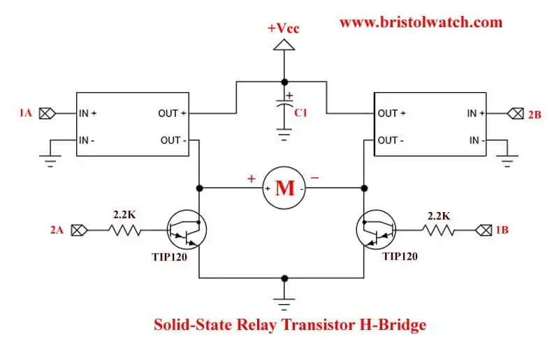
This is the same except two of the solid state relays with bipolar transistors or MOSFETs.
#define SW1 2
#define SW2 3
#define LED1 9
#define LED2 10
#define LED3 11
#define pot 0

// HIGH = 1 and LOW = 0

#define ON 1
#define OFF 0

byte temp;

void setup() {
  pinMode(LED1, OUTPUT);
  pinMode(LED2, OUTPUT);
  pinMode(LED3, OUTPUT);
  pinMode(SW1, INPUT);
  digitalWrite(SW1, HIGH); // pull up on
  pinMode(SW2, INPUT);
  digitalWrite(SW2, HIGH); // pull up on

}

void loop() {
  delay(100);
  if ( S1() && !S2() ) {
    delay(200);
    if (S2()) { } // do nothing
    else digitalWrite(LED1, 1);
  }
  else digitalWrite(LED1, 0);

  if ( S2() && !S1() ) {
    delay(200);
    if ( S1() ) { } // do nothing
    else digitalWrite(LED2, 1);
  }
  else digitalWrite(LED2, 0);

  // power enable
  if ( S1() && S2() ) {
    byte temp = !digitalRead(LED3);
    digitalWrite(LED3, temp);
    while ( S1() || S2() ) {}
  } // end if
} // end loop

// returns 1 if switched pressed
byte  S1(void)   {
  if (digitalRead(SW1) != 1)   return 1;
  // or use (digitalRead(SW1) == 0)
  // 1 is a HIGH
  else return 0;
}

// returns 1 if switched pressed
byte  S2(void)   {
  if (digitalRead(SW2) != 1)   return 1;
  else return 0;
}
- Arduino IF Statement Code Examples
- Arduino Solid State Relay Motor Enable Control
- Arduino XOR Blinks LED
- Arduino Projects Revisited Revised
- Programming ADS1115 4-Channel I2C ADC with Arduino
- Arduino uses ADS1115 with TMP37 to Measure Temperature
- Connect Arduino to I2C Liquid Crystal Display
- Arduino Reads Temperature Sensor Displays Temperature on LCD Display
- Arduino with MCP4725 12-bit Digital-to-Analog Converter Demo
- Videos
- Arduino with ADS1115 4-Channel 16-bit Analog-to-Digital Converter
- Arduino with MCP4725 12-Bit DAC
- Using Zero-Crossing Detectors with Arduino
- Hardware Interrupts Demo and Tutorial for Arduino
- In Depth Look at AC Power Control with Arduino
- Micro-controller AC Power Control Using Interrupts
- Light Activated SCR Based Optocouplers Circuit Examples
- Solid State AC Relays with Triacs
- YouTube
- Zero-Crossing Detectors Circuits and Applications
- Zero-Crossing Circuits for AC Power Control
- In Depth Look at AC Power Control with Arduino
- Micro-controller AC Power Control Using Interrupts
- YouTube Video for Arduino AC Power Control
- Arduino
- Arduino PWM to Analog Conversion
- Arduino Analog Digital Conversion Voltmeter
- Better Arduino Rotary Encoder Sensor
- Simple 3-Wire MAX6675 Thermocouple ADC Arduino Interface
- YouTube:
- 3-Wire MAX6675 Thermocouple ADC Arduino Interface
- Arduino ADC Voltmeter YouTube video
- Arduino PWM to ADC YouTube video
- Arduino Nano Test Template
- Arduino Solid State Relay Motor Enable Control
- Arduino Blink LED Tutorial
- Arduino SSR Power Enable Program
- SSR Based High Voltage H-Bridge
- Arduino H-Bridge Motor Control Program with LCD Display
- Arduino XOR Blinks LED
- Arduino Motor Control Program Using IF
- ULN2003A Darlington Transistor Array with Circuit Examples
- Tutorial Using TIP120 and TIP125 Power Darlington Transistors
- Driving 2N3055-MJ2955 Power Transistors with Darlington Transistors
- Understanding Bipolar Transistor Switches
- N-Channel Power MOSFET Switching Tutorial
- P-Channel Power MOSFET Switch Tutorial
- H-Bridge Motor Control with Power MOSFETS
- More Power MOSFET H-Bridge Circuit Examples
- Build a High Power Transistor H-Bridge Motor Control