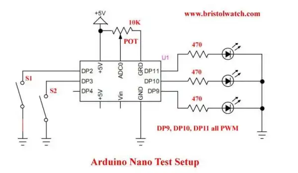
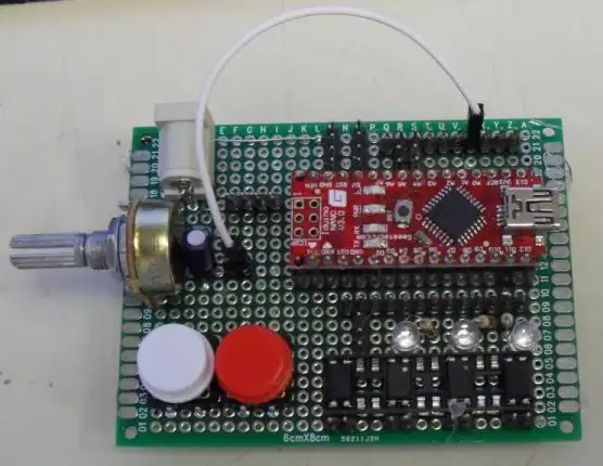
Arduino Nano Test Template
by Lewis Loflin
This is a template for the a series on motor control with the Arduino Nano or similar micro-controller.
It has a small test program that can be cut and pasted to an Arduino compiler.
This is going to combine hardware with software control. This is a tutorial for Arduino beginners.
This is more expanded than in the video.
// Note:

// if (S1()) digitalWrite(LED1, ON);

// is the same as:

// if (S1() == 1) digitalWrite(LED1, ON);

// Any value != 0 is true.

// 0 is false


// Basic template cut and paste.
// Functions S1(0), S2(), and POT()
// LED1(), LED2(), and LED3().

/*
S1 or S2 turn on associated motor
No LCD or power enable LED3
*/

#define SW1 2
#define SW2 3
#define L1 9 // LED DP9
#define L2 10 // LED DP10
#define L3 11 // LED DP11
#define pot 0

// HIGH = 1 and LOW = 0
#define ON 1
#define OFF 0

// define subroutines saves time

// return HIGH when pressed
byte  S1(void)   {
  if (digitalRead(SW1) != 1) return 1;
  else  return 0;
}

// return HIGH when pressed
byte  S2(void)   {
  if (digitalRead(SW2) != 1) return 1;
  else  return 0;
}

// return 0-1023 from ADC
int   POT(void)   {
  int num = analogRead(pot);
  return num;
}

// write LED1
void   LED1(byte temp)   {
  digitalWrite(L1, temp);
}

// write LED2
void   LED2(byte temp)   {
  digitalWrite(L2, temp);
}

// write LED3
void   LED3(byte temp)   {
  digitalWrite(L3, temp);
}

void setup() {
  // put your setup code here, to run once:
  pinMode(L1, OUTPUT);
  pinMode(L2, OUTPUT);
  pinMode(L3, OUTPUT);
  pinMode(SW1, INPUT);
  digitalWrite(SW1, HIGH); // pull up on
  pinMode(SW2, INPUT);
  digitalWrite(SW2, HIGH); // pull up on
}


void loop() {
  delay(100);

  // same as if (S1() == 1)
  if ( S1() ) LED1(ON); // digitalWrite(L1, ON);
  else LED1(OFF); // digitalWrite(L1, OFF);

  // same as if (S2() == 1)
  if ( S2() ) LED2(ON); // digitalWrite(L2, HIGH);
  else LED2(OFF); // digitalWrite(L2, LOW);

} // end loop
- Arduino IF Statement Code Examples
- Arduino Solid State Relay Motor Enable Control
- Arduino XOR Blinks LED
- Arduino Projects Revisited Revised
- Programming ADS1115 4-Channel I2C ADC with Arduino
- Arduino uses ADS1115 with TMP37 to Measure Temperature
- Connect Arduino to I2C Liquid Crystal Display
- Arduino Reads Temperature Sensor Displays Temperature on LCD Display
- Arduino with MCP4725 12-bit Digital-to-Analog Converter Demo
- Videos
- Arduino with ADS1115 4-Channel 16-bit Analog-to-Digital Converter
- Arduino with MCP4725 12-Bit DAC
- Using Zero-Crossing Detectors with Arduino
- Hardware Interrupts Demo and Tutorial for Arduino
- In Depth Look at AC Power Control with Arduino
- Micro-controller AC Power Control Using Interrupts
- Light Activated SCR Based Optocouplers Circuit Examples
- Solid State AC Relays with Triacs
- YouTube
- Zero-Crossing Detectors Circuits and Applications
- Zero-Crossing Circuits for AC Power Control
- In Depth Look at AC Power Control with Arduino
- Micro-controller AC Power Control Using Interrupts
- YouTube Video for Arduino AC Power Control
- Arduino
- Arduino PWM to Analog Conversion
- Arduino Analog Digital Conversion Voltmeter
- Better Arduino Rotary Encoder Sensor
- Simple 3-Wire MAX6675 Thermocouple ADC Arduino Interface
- YouTube:
- 3-Wire MAX6675 Thermocouple ADC Arduino Interface
- Arduino ADC Voltmeter YouTube video
- Arduino PWM to ADC YouTube video
- Arduino Nano Test Template
- Arduino Solid State Relay Motor Enable Control
- Arduino Blink LED Tutorial
- Arduino SSR Power Enable Program
- SSR Based High Voltage H-Bridge
- Arduino H-Bridge Motor Control Program with LCD Display
- Arduino XOR Blinks LED
- Arduino Motor Control Program Using IF
- ULN2003A Darlington Transistor Array with Circuit Examples
- Tutorial Using TIP120 and TIP125 Power Darlington Transistors
- Driving 2N3055-MJ2955 Power Transistors with Darlington Transistors
- Understanding Bipolar Transistor Switches
- N-Channel Power MOSFET Switching Tutorial
- P-Channel Power MOSFET Switch Tutorial
- H-Bridge Motor Control with Power MOSFETS
- More Power MOSFET H-Bridge Circuit Examples
- Build a High Power Transistor H-Bridge Motor Control