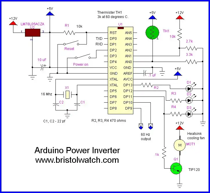
Figure 1.
Arduino Power Inverter Circuits
by Lewis Loflin
Videos for this project:
Arduino power inverter new version: Arduino Power Inverter Revisited.
Arduino power inverter old version: Arduino Power inverter.
In my college classes several of my students plan to study solar energy in particular how power inverters operate. This is a demonstration I setup for my class.
A DC to AC inverter changes 12 or 24 volts DC to 120 or 240 VAC. This is a version of this using the Arduino micro-controller. We have two variations as presented below and will use the exact same micro-controller program not only to drive the power conversion process but to monitor other functions as well. Other features include:
- Monitor battery and input power condition and shutdown if battery voltage is too low. (Less than 11 volts.)
- Monitor the transistor heat sink assembly and turn on a cooling fan if too hot.
- Power up slowly to prevent huge current surges on the 12/24 volts source.
Note: this does not output a sine wave. That would require far more complex circuitry to the point it's cheaper to buy an inverter.
Second this outputs 50Hz or 60Hz depending on delays in the software. A commercial unit chops the DC at a high frequency. Then steps it up through a smaller transformer and rectifies and filters the high-frequency AC to DC. This is then chopped to 50Hz or 60Hz AC through a transistor circuit.
This is done to reduce the size and cost of the transformer.
The drive output from digital pins 9 and 10 provide two square waves 180 degrees out of phase. In a normal 60 Hz. the AC half-cycle period is about 8.33 milli-Sec. pulse width. The frequency and pulse width are very important in determining power output. This was very easy to control with the delay routines in the software.
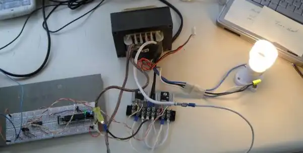
Both diagrams below were tested on a compact fluorescent lamp, a dual tube four-foot shop light, and a Black and Becker power drill. I also tested several transformer types while one transformer designed for a 400 watt uninterruptible power supply (UPS) provided best performance.
In fact this is a recreation of a UPS. I only tested these circuits at 12 volts. The output is a modified square wave.
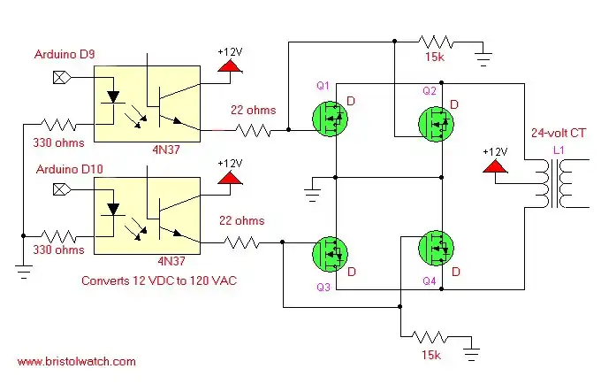
Figure 2.
In figure 2 above we use a 24-volt center-tapped transformer and drive this with N-channel power MOSFETs. I have tried to use bipolar transistors but the performance and output was poor. I used surplus IRFP450s and IRFZ46N types. Both worked well and must be heat sinked. By switching one-half of the transformer side at a time, we recreate the negative/positive half-cycles on the AC output.
If I used a 12 volt center-tapped transformer my output would be 240 volts. The 4N37 opto-isolators serve to isolate the micro-controller from the higher voltages and electrical noise of the output circuits. The MOSFETs can be simply paralleled source to source, drain to drain, and gate to gate for higher currents and power output. The 15k resistors are used to bleed the charges off the MOSFETs gates to turn the device off.
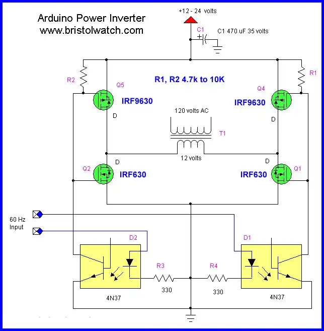
Figure 3.
In figure three I used my H-bridge circuit to drive a transformer. It works a little better than figure 2 and has the advantage of using a non-center-tapped transformer. It does use more power MOSFETs. The MOSFETs can still be wired in parallel as shown in figure 2 for greater power.
Related:
- Opto-Isolated Transistor Drivers for Micro-Controllers
- Build a H-Bridge Motor Control with Power MOSFETs
- Basic Power Transformers
This outputs two square wave pulses to drive inverter circuits using power MOSFETs driving a 24-volt CT transformer to output 120 volts AC.
The period for a 60 Hertz sine wave is 16.666 mSec. So each half-cycle is about 8.3 mSec.
The programs below puts out two square waves one for each half cycle, 180 degrees out of phase.
This also has a soft start feature to limit power surges on power up.
This also measure the voltage on the battery and disables output if the voltage drops below 10 volts.
A 10k and 2.7k are in series and connected to the 12 volt battery bank or power supply (+ 12 connected to 10k) while one end of the 2.7k goes to ground. The 2.7k/10k junction goes to one of the Arduino ADCs and when the battery voltage drops below a half-volt (about 10 volts on the battery) is disabled until battery is recharged.
Download Arduino code arduino_power_inverter.txt.
![]()
- Quick navigation of this website:
- You Tube Channel
- Basic Electronics Learning and Projects
- Basic Solid State Component Projects
- Arduino Microcontroller Projects
- Raspberry Pi Electronics, Programming
- Arduino IR2110 Based H-Bridge HV Motor Control
- Arduino Measures Constant Current Source
- Arduino Controlled Constant Current Source
- Magnetic Driver Board for Stepper Motors
- Arduino
- Arduino DC-AC Power Inverter
- Arduino PWM to Analog Conversion
- Arduino Analog Digital Conversion Voltmeter
- Rotary Encoder Using Arduino Hardware Interrupts
- Better Arduino Rotary Encoder Sensor
- 3-Wire MAX6675 Thermocouple ADC Arduino Interface
- Arduino Stepper Motor Drive Coil Winder
- TB6600 Stepper Motor Driver with Arduino
- Quick navigation of this website:
- Basic Electronics Learning and Projects
- Basic Solid State Component Projects
- Arduino Microcontroller Projects
- Raspberry Pi Electronics, Programming
- Constant Current Circuits with LM317, LM334, etc.
- Experiments with TL431 Shunt Regulator
- LM334 CCS Circuits with Thermistors, Photocells
- LM317 Constant Current Source Circuits
- Photo Detector Devices:
- Photodiode Circuits Operation and Uses
- Photodiode Op-Amp Circuits Tutorial
- Photo Voltaic Tutorial MOSFET Output Solid State Relays
- Transistor Driver Circuits
- Opto-Isolated Transistor Drivers for Micro-Controllers
- MOSFET Transistors, IGBTs Observations
- Added Nov. 16, 2014
- ULN2003A Darlington Transistor Array with Circuit Examples
- Tutorial Using TIP120 and TIP125 Power Darlington Transistors
- Driving 2N3055-MJ2955 Power Transistors with Darlington Transistors
- Understanding Bipolar Transistor Switches
- N-Channel Power MOSFET Switching Tutorial
- P-Channel Power MOSFET Switch Tutorial
- More Power MOSFET H-Bridge Circuit Examples
- Build a High Power Transistor H-Bridge Motor Control
Web site Copyright Lewis Loflin, All rights reserved.
If using this material on another site, please provide a link back to my site.