Rotary Encoder Using Arduino Hardware Interrupts
by Lewis Loflin
YouTube video for this project: Arduino with the HEDS-9000 Rotary Encoder.
Rotary or better known as quadrature decoders have been around for while. They are used in motors to detect speed and direction, while others can be used in many applications that require precise shaft unlimited rotation-including industrial controls, robotics, special purpose photographic lenses, computer input devices such as opto mechanical mice and track balls. More on that at Wikipedia.
Also see Better Arduino Rotary Encoder Sensor
Here I'm concerned with HEDS-9000 that I salvaged in motors from a junked industrial printing machine. The motor is shown in the video and were precise enough to enable the printer to do large industrial blueprints.
The HEDS-9000 uses a single 5-volt supply and produced TTL compatible outputs. In the Arduino sample code below I used one of the two ATMEGA168 external interrupts to detect the rising pulse from channel A then read the logic level of channel B.
The relationship between channels A and B is based on the direction of the motor shaft and the attached code wheel. Also measuring the pulse width can determines the shaft rotational speed. This was displayed on two LEDs.
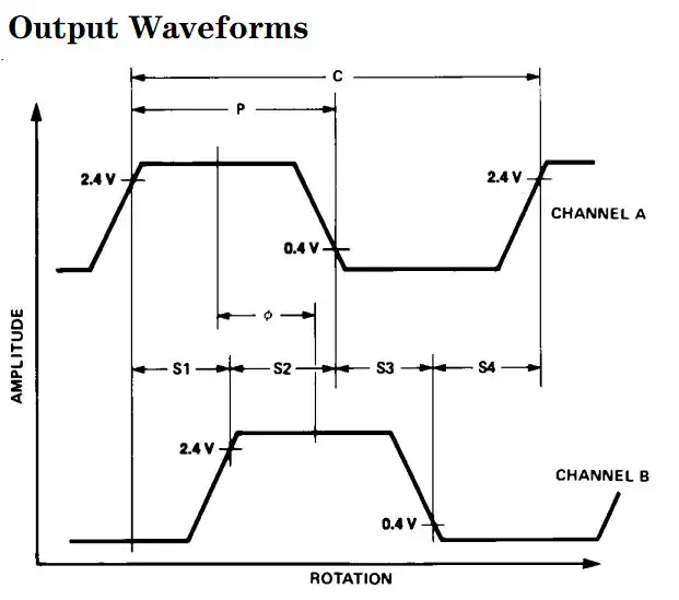
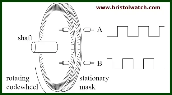
Shown above is the waveform relationship on channel A and B outputs. If we use the positive going edge of waveform A as a reference, we need to read the logic level channel B.
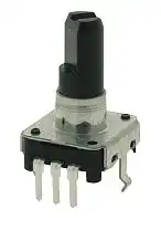
If B is a logical HIGH then we know the direction is counter-clockwise. And if a logical LOW then we know the direction is clockwise. This holds true be it the small front panel unit above or the HEDS-9000 type below.
The HEDS-9000 and 9100 provide sophisticated motion detection at a low cost. Typical applications include printers, plotters, tape drives, and factory automation equipment.
Theory of Operation HEDS-9000
The HEDS-9000 and 9100 are C shaped emitter/detector modules. Coupled with a code wheel, they translate the rotary motion of a shaft into a two-channel digital output.
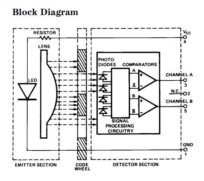
As seen in the block diagram, each module contains a single Light Emitting Diode (LED) as its light source. The light is collimated into a parallel beam by means of a single polycarbonate lens located directly over the LED. Opposite the emitter is the integrated detector circuit.
This IC consists of multiple sets of photo detectors and the signal processing circuitry necessary to product the digital waveforms. The code wheel rotates between the emitter and detector, causing the light beam to be interrupted by the pattern of spaces and bars on the code wheel.
The photodiodes which detect these interruptions are arranged in a pattern that corresponds to the radius and design of the code wheel. These detectors are also spaced such that a light period on one pair of detectors corresponds to a dark period on the adjacent pair of detectors.
The photodiode outputs are then fed through the signal processing circuitry resulting in A, A, B, and B. Two comparators receive these signals and produce the final outputs for channels A and B.
Due to this integrated phasing technique, the digital output of channel A is in quadrature with that of channel B (90 degrees out of phase).
Output waveforms HEDS-9000
The photodiodes which detect these interruptions are arranged in a pattern that corresponds to the radius and design of the code wheel. These detectors are also spaced such that a light period on one pair of detectors corresponds to a dark period on the adjacent pair of detectors.
The photodiode outputs are then fed through the signal processing circuitry resulting in A, A, B, and B. Two comparators receive these signals and produce the final outputs for channels A and B. Due to this integrated phasing technique, the digital output of channel A is in quadrature with that of channel B (90 degrees out of phase).
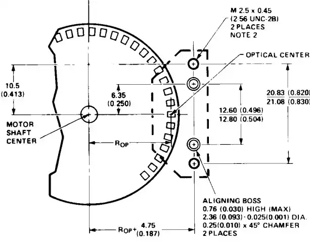
Top view code disk and HEDS-9000
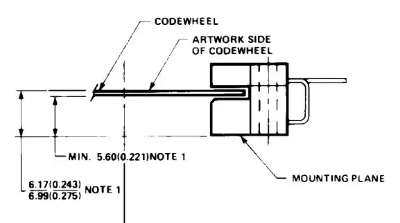
Code Disk side view HEDS-9000
Typical two disk rotary encoder.
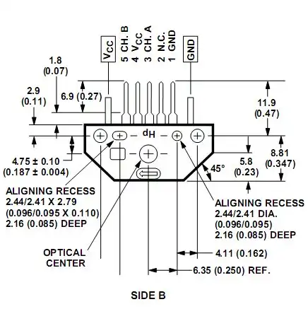
Electrical connections HEDS-9000
Programming Arduino
The most obvious method for Arduino to check the logic level of channel A is by polling or constantly checking the logic level on channel A as the following example code snippet shows:
void loop() {

  while (!digitalRead(CHA)) { } //wait here for HIGH
  byte i = digitalRead(CHB);
  while (digitalRead(CHA))  { } //wait here for LOW
}
I just wasted most of the micro-controller's time simply checking the electrical status of two pins named CHA and CHB. The first while loop idles waiting for CHA to go to HIGH logic level then line two notes the level of CHB after a HIGH is detected on CHA.
Because we don't know the motor speed which determines the pulse width of the HIGH on CHA, we have to wait until CHA goes LOW with line three.
While this will work and will compile just fine it's not very smart coding. But the real solution is to use the Arduino only when CHA goes from LOW to HIGH (or whatever we choose) and do other things in the meantime. The solution is the two hardware interrupts at digital pin 2 (known as INT0) and digital pin 3 (INT1).
Let's look at the following code example:
#define CHA 2
#define CHB 3
#define CW_LED 7
#define CCW_LED 8

volatile int master_count = 0; // universal count
volatile byte INTFLAG1 = 0; // interrupt status flag

void setup() {
  pinMode(CHA, INPUT);
  pinMode(CHB, INPUT);
  pinMode(CW_LED, OUTPUT); // LED connected to pin to ground
  pinMode(CCW_LED, OUTPUT); // LED connected to pin to ground

  attachInterrupt(0, flag, RISING);
  // interrupt 0 digital pin 2 positive edge trigger
}

void loop() {
  if (INTFLAG1)   { // do something on interrupt
   } // end if
    // do other things
}


void flag() {
  INTFLAG1 = 1;
}
The first four lines define the LED connections and the connection to the encoder with channel A being digital pin 2 and channel B being digital pin 3.
The next two lines declare two variables INTFLAG1 and master_count. Volatile means these variables are in static RAM and can be changed and read by all subroutines, interrupt service routines, and the main program loop. Most of setup() is self explanatory and now we come to attachInterrupt(0, flag, RISING).
The Arduino mini (ATMEGA168) that I use has two external hardware interrupts: numbers 0 (on digital pin 2) and 1 (on digital pin 3). The Arduino Mega has an additional four: numbers 2 (pin 21), 3 (pin 20), 4 (pin 19), and 5 (pin 18). That is why I connected CHA to digital pin 2 and CHB to digital pin 3.
Thus with attachInterrupt(0, flag, RISING) the "0" specifies interrupt 0 in digital pin two.
"RISING" specifies the type of electrical signal that will trigger an interrupt:
- RISING to trigger when the pin goes from low to high,
- LOW to trigger the interrupt whenever the pin is low,
- CHANGE to trigger the interrupt whenever the pin changes value,
- FALLING for when the pin goes from high to low.
The reason I chose RISING is because I wanted to trigger an interrupt when CHA went from LOW (0 volts on digital pin 2) to HIGH (5 volts on digital pin 2).
What a hardware interrupt does is tell Arduino to stop whatever it is doing, save the location address in memory (known as a stack), do whatever the interrupt service routine (ISR), in this case called flag, then go right back where it stopped and continue on. The advantage is the micro-controller doesn't waste most of its time checking for HIGH or LOW on a digital pin.
In this program example an interrupt is generated from digital pin 2 when the HEDS-9000 encoder goes from 0 volts to 5 volts (known as a positive edge trigger). The main program will stop, save the location where it stopped on the stack, jump to the ISR routine flag(), which sets the volatile variable INTFLAG1 to 1, then go back and continue on where it stopped after pulling the location address from the stack.
At this point the line if (INTFLAG1) checks to see if INTFLAG1 is a 1 (set) then does whatever commands are between the braces { }. After that continues on with other parts of the program. Now let's add some more to this.
void loop() {
  if (INTFLAG1)   {
    byte temp = digitalRead(CHA);
    digitalWrite(CW_LED, temp);
    temp = digitalRead(CHB);
    digitalWrite(CCW_LED, temp);
    INTFLAG1 = 0; // clear flag
   } // end if

} // end loop
What the above program does is turn on the CW and CCW LEDs based on the electrical states on CHA and CHB giving us a visual indication of direction. The line INTFLAG1 = 0; simply clear the INTFLAG1 until the next interrupt. This doesn't work very well, there has to be a better way as shown below.
The interrupts can be disabled at any time with the detachInterrupt(0) for time consuming for sensitive programs, which can be reattached with attachInterrupt(0, flag, RISING); anywhere in the program. Note with the interrupt off one might miss some interrupts!
The final program below outputs the direction as indicated by the LEDs and on the serial monitor the values of the master_count variable. As I turn the motor shaft CW the count increases, and CCW decreases. Have fun!
/*
Demonstrates use of rotary encoder for motor
direction and distance.
*/

#define CHA 2
#define CHB 3
#define CW_LED 8
#define CCW_LED 7

volatile int master_count = 0; // universal count
volatile byte INTFLAG1 = 0; // interrupt status flag

void setup() {
  pinMode(CHA, INPUT);
  pinMode(CHB, INPUT);
  pinMode(CW_LED, OUTPUT); // LED connected to pin to ground
  pinMode(CCW_LED, OUTPUT); // LED connected to pin to ground

  Serial.begin(9600);
  Serial.println(master_count);

  attachInterrupt(0, flag, RISING);
  // interrupt 0 digital pin 2 positive edge trigger
}

void loop() {

  if (INTFLAG1)   {
       Serial.println(master_count);
       delay(500);
     INTFLAG1 = 0; // clear flag
} // end if


} // end loop


void flag() {
  INTFLAG1 = 1;
  // add 1 to count for CW
  if (digitalRead(CHA) && !digitalRead(CHB)) {
    master_count++ ;
    digitalWrite(CW_LED, HIGH);
    digitalWrite(CCW_LED, LOW);
  }
  // subtract 1 from count for CCW
  if (digitalRead(CHA) && digitalRead(CHB)) {
    master_count-- ;
    digitalWrite(CW_LED, LOW);
    digitalWrite(CCW_LED, HIGH);
  }
}
- Quick navigation of this website:
- Basic Electronics Learning and Projects
- Basic Solid State Component Projects
- Arduino Microcontroller Projects
- Raspberry Pi Electronics, Programming
Stepper Motors
- Easy Driver Micro-Stepper Controller to Arduino
- Unipolar Stepper Motor with a Arduino
- Considerations for Using Stepper Motors
- Connecting the Arduino to a L298N H-Bridge
- L298N Motor Controller Theory and Projects
- TA8050 H-Bridge Motor Controller
- Battery Charger related:
- Solar Panel Charge Controller Using Arduino
- Solar Panel Battery Charge Controller Using Arduino
- Solar Panel Battery Charge Controller Switching Circuit
- Arduino AC Power Control Tutorial
- Rotary Encoder Using Arduino Hardware Interrupts
- Arduino Controlling 74C164 Shift Register
- Arduino Interface MC3479 Stepper Motor Controller
Serial LCD Display and assorted Sensors
- Arduino LCD Display using 74164 Shift Register
- Arduino LCD Display with DS18B20
- Arduino LCD Display with DHT11 Sensor
- Arduino with MM5451 LED Display Driver
- Arduino MAX7219 Operates 8X8 LED Matrix
- Arduino RTC Clock MAX7219 LED Display
- BCD Conversion with MAX7219
- Hatching Chicken Eggs with Arduino
- Arduino TMP37 Temperature Sensor
- Arduino TMP37 Temperature Sensor Tutorial
- Testing the Keyes IR Sensor Module with Arduino
- Arduino to MCP23016, LCD Display
- Time-Date with Arduino, LCD Display, DS1307 RTC
- Controlling Driveway Lights with the Arduino
- TSL230R Light to Frequency Converter
- Arduino with MCP23016 I/O Expander
- Arduino DS1307 Real Time Clock
- Arduino with 24LC08 Serial EEPROM
- MC3479 Stepper Motor Controller with Arduino
Web site Copyright Lewis Loflin, All rights reserved.
If using this material on another site, please provide a link back to my site.