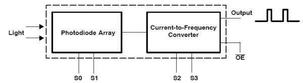
Internal Schematic
Arduino Interfacing TSL230R Light Frequency Converter
by Lewis Loflin
Note as of 2023 this part is obsolete and hard to find.
The purpose of this page is to demonstrate the operation of the TSL239R light to frequency converter. The device outputs a 50% duty square wave whose frequency is proportional to light intensity. Not only can the TSL230R be used for detecting light intensity to adjust say lighting levels, it's sensitive enough to be a motion detector by measuring small changes in light level due to the motion of an object.
The program below is very basic in measuring the positive on time of the square wave and calculating the frequency, acting as a crude frequency counter. The same basic setup can be used with any number micro-controllers.
Download spec sheet (PDF)
Sensitivity
The TSL230R provides three levels of sensitivity (in addition to
an off state) to accommodate the measurement of nearly any
light intensity.
This is accomplished by dividing the photodiode
array into sections which can be enabled or disabled to provide
the needed sensitivity. The sensitivity is set by setting the
appropriate levels on control pins S0 and S1.
S1    S0    Sensitivity
0     0     off
0     1     x 1
1     0     x 10
1     1     x 100
Output Frequency Scaling
The raw output frequency can vary from approximately 1 Hz to over 1 Mhz. Since the top frequency output is so high that some micro-controllers, such as the BASIC Stamp, are unable to measure the frequency, two pins (S2 and S3) on the TSL230R are provided as a frequency divider setting making it possible to measure the output frequency with slower micro-controllers.
S3   S2   Divide output by
0     0   1
0     1   2
1     0  10
1     1  100
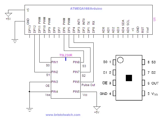
Basic Schematic
Pin out on TSL230R:
1 S0 Sensitivity select input
2 S1 Sensitivity select input
3 OE Output Enable
4 GND Ground 0 V
5 VCC/VDD +3 to +5 VDC supply voltage
6 Scaled-frequency output
7 S2 Scaling select input
8 S3 Scaling select input
View output on I2C lcd Display.
Arduino code for this project: arduino_tsl230r.txt.
- Quick navigation of this website:
- Basic Electronics Learning and Projects
- Basic Solid State Component Projects
- Arduino Microcontroller Projects
- Raspberry Pi Electronics, Programming
Stepper Motors
- Easy Driver Micro-Stepper Controller to Arduino
- Unipolar Stepper Motor with a Arduino
- Considerations for Using Stepper Motors
- Connecting the Arduino to a L298N H-Bridge
- L298N Motor Controller Theory and Projects
- TA8050 H-Bridge Motor Controller
- Battery Charger related:
- Solar Panel Charge Controller Using Arduino
- Solar Panel Battery Charge Controller Using Arduino
- Solar Panel Battery Charge Controller Switching Circuit
- Arduino AC Power Control Tutorial
- Rotary Encoder Using Arduino Hardware Interrupts
- Arduino Controlling 74C164 Shift Register
- Arduino Interface MC3479 Stepper Motor Controller
Serial LCD Display and assorted Sensors
- Arduino LCD Display using 74164 Shift Register
- Arduino LCD Display with DS18B20
- Arduino LCD Display with DHT11 Sensor
- Arduino with MM5451 LED Display Driver
- Arduino MAX7219 Operates 8X8 LED Matrix
- Arduino RTC Clock MAX7219 LED Display
- BCD Conversion with MAX7219
- Hatching Chicken Eggs with Arduino
- Arduino TMP37 Temperature Sensor
- Arduino TMP37 Temperature Sensor Tutorial
- Testing the Keyes IR Sensor Module with Arduino
- Arduino to MCP23016, LCD Display
- Time-Date with Arduino, LCD Display, DS1307 RTC
- Controlling Driveway Lights with the Arduino
- TSL230R Light to Frequency Converter
- Arduino with MCP23016 I/O Expander
- Arduino DS1307 Real Time Clock
- Arduino with 24LC08 Serial EEPROM
- MC3479 Stepper Motor Controller with Arduino
Web site Copyright Lewis Loflin, All rights reserved.
If using this material on another site, please provide a link back to my site.