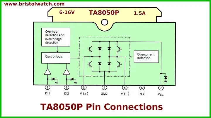
Pin out on the Toshiba TA8250
Arduino Operating TA8050 H-Bridge Motor Controller
by Lewis Loflin
The purpose of this tutorial is the demonstrate using the ATMEGA168/Arduino to control the speed and direction of a 12 volt DC using an "h" bridge.
We will make use of pules-width modulation (PWM) to control motor speed. In this case we are using Toshiba TA8050 integrated circuit and a home-built "H" bridge using power MOSFETs.
An H-bridge is an electronic circuit which enables a voltage to be applied across a load in either direction. These circuits are often used in robotics and other applications to allow DC motors to run forwards and backwards. H-bridges are available as integrated circuits, or can be built from discrete components or even relays and manual switches.
A solid-state H-bridge is typically constructed using reverse polarity devices such as PNP bipolar transistors or P-channel MOSFETs connected to the positive voltage bus and NPN bipolar junction or N-channel MOSFETs connected to the negative voltage bus).
Pulse-width modulation (PWM) is a very efficient way of providing intermediate amounts of electrical power between fully on and fully off. A simple power switch with a typical power source provides full power only when switched on.
PWM is a comparatively-recent technique made practical by modern high speed electronic power switches.
This goes beyond mere thermostats that cycle on and off at very slow rates. An inexpensive solid-state lamp dimmer controls the amount of time each AC half-cycle (120 Hertz) is on. See Basic Triacs and SCRs
In the past, when only partial power was needed (such as for a sewing machine motor), a variable power resistor (foot-controlled; a rheostat) connected in series with the motor adjusted the amount of current flowing through the motor. Part of the power was wasted as heat in the resistor element. Auto transformers could be used but are costly.
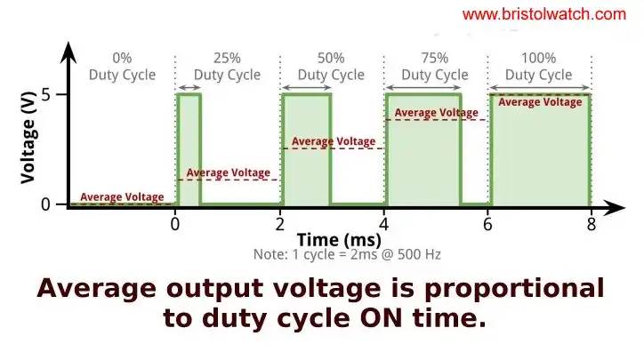
Average voltage is proportional to duty cycle.
See Pulse Width Modulation Power Control for Microcontrollers
The term duty cycle describes the proportion of on-time versus off-time. Duty cycle is expressed in percent, 100% being fully on 0% is fully off.
In the Arduino has six digital pins (3, 5, 6, 9, 10, 11) that can be programmed as 8-bit PWMs. Using the command analogWrite(pin, value) where 'pin' is the output pin and 'value' is a number from 0 to 255.
In the above example we could have a frequency (f) of 1000 Hertz which give us the period or cycle time (1/f = T) of 1 millisecond or 1000 microseconds. If the digital pulse is HIGH for 250 microseconds and LOW for 750 microseconds we have a duty cycle of Ton/T X 100 = 250/1000 X 100 = 25%.
For example an analogWrite(3, 0) outputs zero volts or fully off on digital pin 3. And analogWrite(255, 3) outputs 5 volts or fully on with digital pin 3. A value of 128 produces a square wave that's 50% on and 50% off for a duty cycle of 50%.
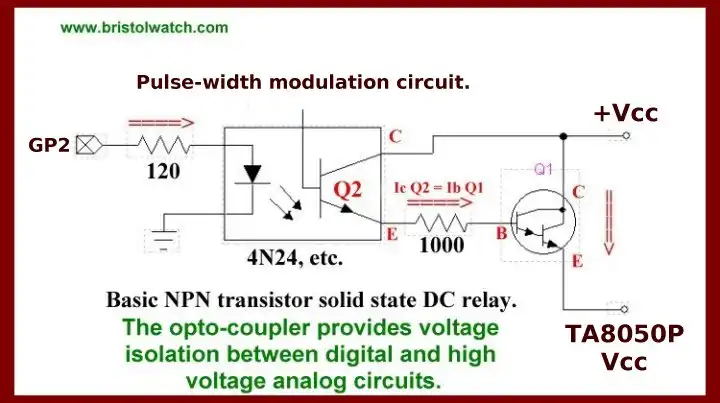
In the example below the motor would run somewhere around half-speed without wasting half the power as heat if we had used a variable resistor in series. See Q1 in schematic below.
Also see:
- Arduino Analog to Digital Conversion Voltmeter
- Arduino Pulse-Width Modulation Digital to Analog Conversion
PWM works well with digital controls because of its on/off nature. Finally a simple resistor/capacitor low pass filter on the output pin will produce an analog voltage of 0 to 5 volts depending on duty cycle.
You do not need to call pinMode() to set the pin as an output before calling analogWrite(). The PWM outputs generated on pins 5 and 6 will have higher-than-expected duty cycles.
This is because of interactions with the millis() and delay() functions, which share the same internal timer used to generate those PWM outputs.
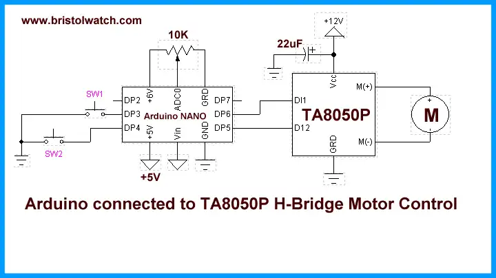
TA8050 to Arduino hookup diagram
Shown above is the TA8050P a 1.5 A motor driver that directly drives a DC motor. Inputs Dl1 and Dl2 are combined to select one of forward, reverse, stop, and brake modes. Since the inputs are TTL-compatible, this IC can be controlled directly from a CPU or other control system. The IC also has various protective functions. See TA8050P 'H' Bridge Motor Controller
Download Arduino code arduino_pwm_hb.txt.
- Quick navigation of this website:
- Basic Electronics Learning and Projects
- Basic Solid State Component Projects
- Arduino Microcontroller Projects
- Raspberry Pi Electronics, Programming
Stepper Motors
- Easy Driver Micro-Stepper Controller to Arduino
- Unipolar Stepper Motor with a Arduino
- Considerations for Using Stepper Motors
- Connecting the Arduino to a L298N H-Bridge
- L298N Motor Controller Theory and Projects
- TA8050 H-Bridge Motor Controller
- Battery Charger related:
- Solar Panel Charge Controller Using Arduino
- Solar Panel Battery Charge Controller Using Arduino
- Solar Panel Battery Charge Controller Switching Circuit
- Arduino AC Power Control Tutorial
- Rotary Encoder Using Arduino Hardware Interrupts
- Arduino Controlling 74C164 Shift Register
- Arduino Interface MC3479 Stepper Motor Controller
Serial LCD Display and assorted Sensors
- Arduino LCD Display using 74164 Shift Register
- Arduino LCD Display with DS18B20
- Arduino LCD Display with DHT11 Sensor
- Arduino with MM5451 LED Display Driver
- Arduino MAX7219 Operates 8X8 LED Matrix
- Arduino RTC Clock MAX7219 LED Display
- BCD Conversion with MAX7219
- Hatching Chicken Eggs with Arduino
- Arduino TMP37 Temperature Sensor
- Arduino TMP37 Temperature Sensor Tutorial
- The following use obsolete parts and are kept as a reference.
- Testing the Keyes IR Sensor Module with Arduino
- Arduino to MCP23016, LCD Display
- Time-Date with Arduino, LCD Display, DS1307 RTC
- Controlling Driveway Lights with the Arduino
- TSL230R Light to Frequency Converter
- Arduino with MCP23016 I/O Expander
- Arduino DS1307 Real Time Clock
- Arduino with 24LC08 Serial EEPROM
- MC3479 Stepper Motor Controller with Arduino
Web site Copyright Lewis Loflin, All rights reserved.
If using this material on another site, please provide a link back to my site.