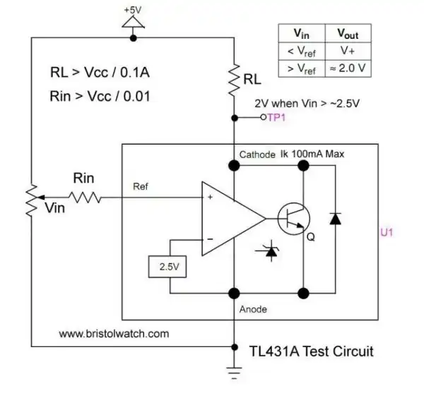
Fig. 1 TL431 shunt voltage regulator internal block diagram.
TL431 Over-Voltage, Under-Voltage Detectors
by Lewis Loflin
In Fig. 1 illustrates the TL431 internal block diagram. The reality is the TL431 is a comparator circuit with an internal 2.5V reference and an output NPN transistor.
The device is rated at 100mA anode-to-cathode max with a max voltage of 34 volts. Vref input is limited to 10mA. Theses devices can be used to construct voltage references, shunt power supply regulation, constant current sources, etc. From the specification sheet:
The TL431A, B integrated circuits are three−terminal programmable shunt regulator diodes. These monolithic IC voltage references operate as a low temperature coefficient zener which is programmable from Vref (2.5V) to 36 V with two external resistors. These devices exhibit a wide operating current range of 1.0mA to 100 mA with a typical dynamic impedance of 0.22 Ohms.
The characteristics of these references make them excellent replacements for zener diodes in many applications such as digital voltmeters, power supplies, and op-amp circuitry. The 2.5 V reference makes it convenient to obtain a stable reference from 5.0 V logic supplies, and since the TL431A, B, operates as a shunt regulator, it can be used as either a positive or negative voltage reference.
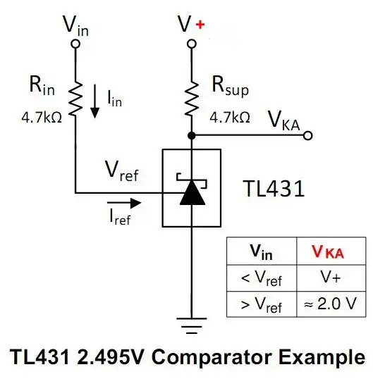
Fog. 2 TL431 2.495V comparator example.
Fig. 2 is a basic comparator configuration for the TL431. The range is simply if Vin > 2.5V then the TL431 will switch on. Vka will go to ~2V.
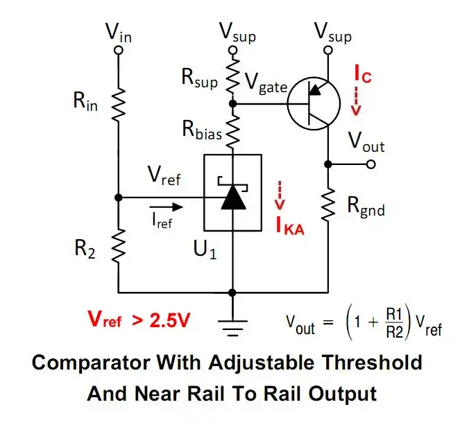
Fig. 3 TL431 comparator circuit with adjustable threshold.
Fig. 3 uses a resistor network to extend the voltage range. The power supply is separate from Vin. The supply can be 5-volts to connect to a microcontroller. This will not work on 3.3V systems.
Vin with the right resistors can be used to 30V. The Rbias resistor limits base current for the PNP transistor switch.
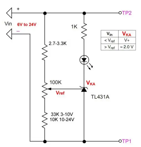
Fig. 4 Example TL431 over-voltage detector.
This is a circuit I found on the internet. The LED will turn on when the Vin voltage, though the resistor network, is greater than the Vref voltage. Below that the LED will be off.
I built and dislike this circuit for two reasons. The Vin voltage is also the supply voltage. At low voltages the LED is dim due to 2V on the TL431 cathode when turned on.
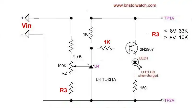
Fig. 5 Better TL431 over voltage detector with single supply.
The above circuit with the extra transistor eliminates the dim LED problem. Vin also acting as V++ can still create problems.
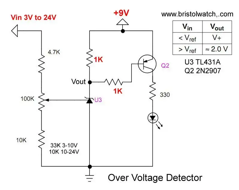
Fig. 6 TL431 over-voltage circuit.
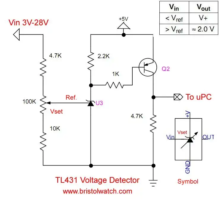
Fig. 7
Because the power supply is severed from Vin, with a 5-volt supply one can connect directly to Arduino or other microcontroller.
A HIGH output indicates an over-voltage condition based on the adjustment of the 100K potentiometer.
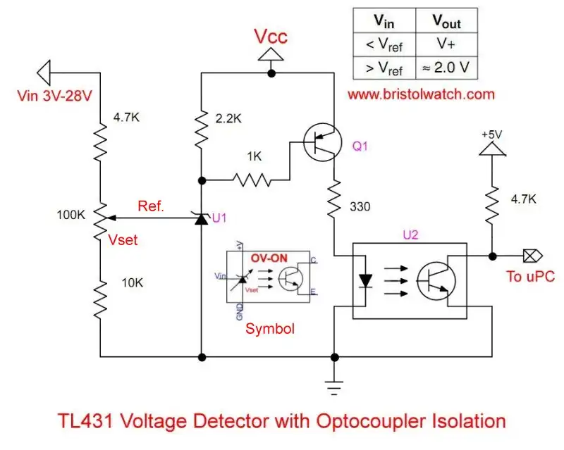
Fig. 8 TL431 voltage level detector with optocoupler voltage isolation.
Fig. 8 is identical to Fig. but has added an optocoupler for voltage and noise isolation. In this example Vin can range for 3V to 31V, while Vcc be higher than 5-volts, for example 12-volts.
The only difference is the optocoupler output goes LOW when Q1 is switched on when Vin exceeds the trip voltage set by the 100K potentiometer.
Figures 6 and & can be used as over-voltage or under-voltage detectors by reading the logic level output.
To set up the over-voltage level connect a variable power supply to Vin, adjust the 100K potentiometer to the desired over-voltage detection level where the LED just turns on.
For under voltage adjust to desired operating voltage. When the voltage drop the LED will turn off.

Fig. 9 TL431 under-voltage detector with opto-coupler.
Fig. is a demo circuit that will turn an LED when Vin drops below the value set by the 100K pot. An optocoupler is connected in series with the indicator LED for connection to a microcontroller.
- Experiments with TL431 Shunt Regulator
- TL431A Precision Current Regulator Circuits
- TL431A Based Current Limiter Constant Current Source Circuits
- TL431A Shunt Regulator Circuits
- Using TL431A Li-Ion Battery Charger Tutorials
- TL431A Lithium-Ion Cell Charging Circuits
- Charging Multi-Cell Lithium-Ion Battery Packs
- TL431 Over-Voltage, Under-Voltage Detector Circuits
- TL431A Constant Current Source Working Circuits Demo
Related YouTube video TL431A Lithium-Ion Cell Charging Circuits
Related YouTube video TL431 Battery Charger Circuit Calculations Revised
Related YouTube video TL431 10-Volt Charger Short Version
Related YouTube video Charging, Charge-Balancing 18V Li-Ion Battery with TL431
Related YouTube video 18.5V Li-Ion Battery Charger with TL431 (short)
- Arduino Measures Current from Constant Current Source
- Constant Current Source Theory Testing
- Arduino Controlled Power Constant Current Source
- LM317 Adjustable Current Boost Power Supply
- Constant Current Circuits LM334, LM317
- Build LM317 0-34 Volt Power Supply
- LM334 Constant Current Source with Resistive Sensors
- LM317 High Power Constant Current Source Circuit
- LM317 Constant Current Source Circuits
- Test SCRs and Triacs
- Basic MOSFET Transistor Test Circuits
- High Voltage MOSFET Switching Circuits
- 3 Amp LM741 Op-Amp Constant Current Source
- Current Limiter Testing of Zener Diodes
- Current Limiter for Opto-Coupler Inputs
- LM317 CCS for Light Emitting Diodes
Other Circuits
- Hall Effect Magnetic Switches and Sensors
- Comparator Theory Circuits Tutorial
- ULN2003A Darlington Transistor Array with Circuit Examples
- Transistor-Zener Diode Regulator Circuits
- AC Power Supply Rectification
- Coils for Highly Selective Crystal Radio
- Neon (NE-2) Circuits You Can Build
- Photodiode Circuits Operation and Uses
- Photodiode Op-Amp Circuits Tutorial
Web site Copyright Lewis Loflin, All rights reserved.
If using this material on another site, please provide a link back to my site.