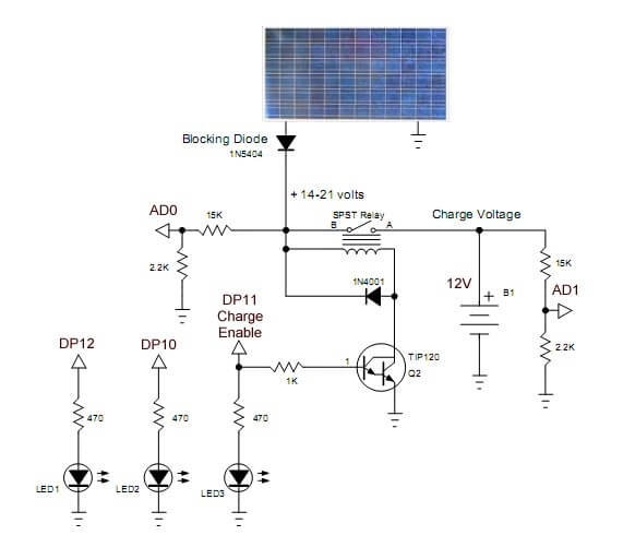
Fig. 1 Charger circuit using 12-volt DC relay.
PICAXE 18M2 Solar Panel Charge Controller
The following is the PICAXE version of the Arduino Solar Panel Charge Controller. While the electronics is identical, the programming was very different. The main problem for the PICAXE was the inability of the software to do compound 'if' statements: if ((x > y) & (y < CP) & (x > CP)) . I had to break that into three different statements then had to add a fourth.
Otherwise it worked just the same. See Arduino Solar Panel Charge Controller for additional schematics.
Related material:
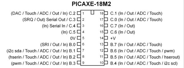
PICAXE 18M2 used here..
#rem

Picaxe solar panel charge controller

Purpose: to cycle to charge voltage on/off and to check other aspects
such as solar panel input voltage when charging lead-acid batteries.

#picaxe 18m2 ; type chip used

 B.4 LED1 indicator 'bad' meaning the
 input voltage below charging voltage when on.

 B.7 turns on charge switch transistor.
 Will blink on/off with charge cycle. LED3 will turn on
 during the charge cycle.(Charge enable DP11)

 B.5 LED2 indicator fully charged battery. (DP10)

 A 10-bit analog-to-digital converter (ADC)
 has a step voltage of about 4.9 mV
 over a 5-volt range. This relates to the
 charge point (CP) variable.

 To measure input voltage from the solar panel and the voltage on the
 battery we use a voltage divider to drop the voltage below 5-volts.

 This uses two resistor voltage dividers (15k and 2.2k)
 which produces a voltage
 of about 1.7 - 1.9 volts when fully charged. This equates
 to about decimal 346 - 400 from the ADC and is
 compared to the charge point variable CP.

 Note line "chon = CP - y * 1000" when uncommented
 the charge 'on' time will decrease
 gradually as battery is more charged.
 When fully charged the charge voltage
 is disabled.

 The variables chon (charge on time) and choff
 (charge off time) can be preset to any value.

 One can experiment with this CP value.
  Too small, battery won't fully charge.
 Too large, battery will over charge.

 The voltage input is connected to C.1 (AD0  in schematic)
 while the voltage on the battery
 is monitored at C.0 (AD1 in schematic ).

 This same circuit can be used with a 24-volt
  system by changing the 15K to 27K,
 and using a 24-volt relay.

 The power for the PICAXE itself can be obtained
 from the battery bank under charge
 through a 5-volt regulator or separate supply.
 Note if the battery bank is completely
 dead the circuit won't function with no power t
 o the Microcontroller. A separate source
 for the controller is recommended.

 This circuit will also work using a power supply
 instead of a solar panel as a simple battery charger.

#endrem

symbol voltage_in = C.1
symbol voltage_out = C.0

symbol LED1 = B.5
symbol LED2 = B.4
symbol charge_enable = C.7


LOW LED1
LOW LED2
LOW charge_enable

symbol x = w0
symbol y = w1


symbol chon = w2
symbol choff = w3

chon = 2000
choff = 6000

symbol CP = w4 ; charge point variable

symbol temp = B10

CP = 340

main:

temp = 0

readadc10 voltage_in, x  ; voltage from solar panel
readadc10 voltage_out, y ; voltage on battery


 if x <= CP then HIGH LED1 else LOW LED1 endif
  ;LED off indicates good input voltage


 if y >= CP then HIGH LED2 else LOW LED2 endif
  ;LED on means battery is charged


    if x > CP then inc temp endif
    if y < x then inc temp endif
    if y < CP then inc temp endif


    if temp = 3 then gosub charge
    ; turn on charge cycle if voltage
    ; input good AND battery voltage low.

    goto main


    charge: ; charge enable routine


    HIGH charge_enable; // turn on voltage to battery
   ; chon = CP - y * 1000 ;uncomment this for variable charge rate
    pause chon;  wait
    LOW charge_enable ;turn off charge enable
    pause choff; wait for charge to equalize

    goto main
- Comparator Circuits:
- Comparator Theory Circuits Tutorial
- Comparator Hysteresis and Schmitt Triggers
- Voltage Comparator Information And Circuits
- Looking at Window Comparator Circuits
- Analog Battery Charger Uses Comparators
- Battery Charger related:
- Solar Panel Charge Controller Using Arduino Microcontroller
- Solar Panel Charge Controller Using PICAXE Microcontroller
- Solar Panel Battery Charge Controller Using Arduino
- Solar Panel Battery Charge Controller Switching Circuit
- Solar Battery Charger videos:
- Solar Panel Battery Charge Controller Operation
- Solar Panel Battery Charge Controller Circuitry
- Solar Panel Battery Charge Controller Programming
- Tutorial Arduino Measure Current with ACS712 Hall Sensor
Picaxe Micro-controller Projects!
The PICAXE series of micro-controllers rank as the easiest and most cost effective way to use Microchip processors. I wanted an easier and less expensive way to introduce my students to the "PIC" micro-controller. Here I hope to get those starting out past poorly written literature and lack of simple working code examples.
- PICAXE Related videos Oct. 2016:
- Tutorial: Programming-Using PICAXE-18M2 Microcontroller
- How to setup PICAXE Pulse Width Modulation
- PICAXE TA8050P H-Bridge with Motor Control
- PICAXE TA8050P H-Bridge with Motor Speed Control
- PICAXE-18M2 Operates MOSFET H-Bridge
- PICAXE-18M2 Uses MCP23016 GPIO Expander
- Solar Panel Charge Controller Using PICAXE Microcontroller
- Exploring the PICAXE Micro-Controller
- Understanding Micro-Controller Input/Output Ports
- Using the 74HC165 Shift Register with the PICAXE Micro-Controller
- Connecting the 74HC595 Shift Register to PICAXE Micro-controller
- Using 7-Segment Displays with the PICAXE Micro-Controller
- Potentiometers and Analog-to-Digital Conversion with the PICAXE
- Pulse-Width Modulation Motor Speed Control and the PICAXE Micro-Controller
- Connecting the PICAXE to the DS1307 Real Time Clock
- Connecting the PICAXE to an External EEPROM (24LC08)
- Connecting a Servo to a PICAXE
- Connecting the TLC548 to the PICAXE
- Connecting the Ad5220 Digital Potentiometer to the PICAXE
See How I got into Electronics