Fig. 1 Schematic to my home built test board minus I/O resistors.
PICAXE 18M2 Micorcontroller Operates TLC548 Serial ADC
Here we will read the analog-to-digital values from a TLC548 ADC with PICAXE and display those values on the terminal. The second program is a variation of Analog-to-Digital Conversion with the PICAXE demo except we use an external ADC and not the internal units.
Fig. 2
Fig. 2 shows the electrical connections between the PICAXE 18M2 and Ad5220. C.0 is electrical pin 17 and C.1 is electrical pin 18 on the PICAXE chip.
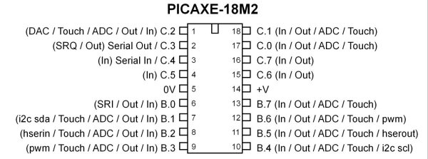
Fig 3 PICAXE 18M2.
Program 1
#rem

TLC548 8-bit ADC demo

Program will read value from TLC548
and display on terminal.

Pins on the TLC548:

1 -> Ref + -> connect to Vcc
2 -> analog in
3 -> Ref - -> connect to GND
4 -> GND

5 -> CS-NOT -> chip select active LOW
6 -> DATA OUT
7 -> CLK
8 -> Vcc

Page references pertain to PICAXE Manual 2 Basic Commands

#endrem


#picaxe 18M2 ; type chip used

#terminal 4800 ;set baud rate serial terminal and open


setfreq m4  ; set internal resonator to 4mHz p. 221

symbol Data_In = pinC.0
symbol CLK = C.1
symbol CS = C.2
; CS connected to ground.

symbol val = b0
symbol temp = b1
symbol i = b2
symbol j = b3

HIGH CS
LOW CLK


main:

LOW CS

   for i = 1 to 8
     HIGH CLK
     pause 1
     if Data_in = 1 then gosub OR1
     if Data_in = 0 then gosub OR0
     LOW CLK
   next i

HIGH CS
; convert val to three ASCII char p. 36
bintoascii val,b6,b7,b8
; send char to terminal followed by LF-CR p. 210
sertxd(b6,b7,b8,13,10) ; 13,10 -> LF-CR

pause 200

goto main


OR1:
;bitwise OR 0x01 shift one place left
val = val | %00000001 * 2
return

OR0:
;bitwise OR 0x00 shift one place left
val = val * 2
return
Connect the three LEDs as shown.
Program 2
In the code below three LEDs (with 220 ohm dropping resistors) are connected in the "sink" configuration shown above. The program examines the value returned form the ADC and lights the corresponding LED based on that number. Refer to Analog-to-Digital Conversion with the PICAXE.
symbol LED1 = C.2  ; to electrical pin 1
symbol LED2 = C.7  ; to electrical pin 16
symbol LED3 = C.6  ; to electrical pin 15


symbol Data_In = pinC.0
symbol CLK = C.1
symbol CS = C.2
; CS connected to ground.

symbol val = b0
symbol temp = b1
symbol i = b2
symbol j = b3

HIGH CS
LOW CLK
main: ; start program

LOW CS

   for i = 1 to 8
     HIGH CLK
     pause 1
     if Data_in = 1 then gosub OR1
     if Data_in = 0 then gosub OR0
     LOW CLK
   next i

HIGH CS

   if val > 120 then top
   ;  jump to label top if true
   if val > 70 AND val < 120 then middle
   ; jump to label middle if true
   if val < 70 then bottom
   ; jump to label bottom if true

goto main  ;jump back to the start


top:   ; label
HIGH LED1
LOW LED2
LOW LED3
goto main ; done jump back to start

middle:   ; label
LOW LED1
HIGH LED2
LOW LED3
goto main  ; done jump back to start

bottom:  ; label
LOW LED1
LOW LED2
HIGH LED3
goto main  ; done jump back to start


OR1:
;bitwise OR 0x01 shift one place left
val = val | %00000001 * 2
return

OR0:
;bitwise OR 0x00 shift one place left
val = val * 2
return
Picaxe Micro-controller Projects!
The PICAXE series of micro-controllers rank as the easiest and most cost effective way to use Microchip processors. I wanted an easier and less expensive way to introduce my students to the "PIC" micro-controller. Here I hope to get those starting out past poorly written literature and lack of simple working code examples.
- PICAXE Related videos Oct. 2016:
- Tutorial: Programming-Using PICAXE-18M2 Microcontroller
- How to setup PICAXE Pulse Width Modulation
- PICAXE TA8050P H-Bridge with Motor Control
- PICAXE TA8050P H-Bridge with Motor Speed Control
- PICAXE-18M2 Operates MOSFET H-Bridge
- PICAXE-18M2 Uses MCP23016 GPIO Expander
- Solar Panel Charge Controller Using PICAXE Microcontroller
- Exploring the PICAXE Micro-Controller
- Understanding Micro-Controller Input/Output Ports
- Using the 74HC165 Shift Register with the PICAXE Micro-Controller
- Connecting the 74HC595 Shift Register to PICAXE Micro-controller
- Using 7-Segment Displays with the PICAXE Micro-Controller
- Potentiometers and Analog-to-Digital Conversion with the PICAXE
- Pulse-Width Modulation Motor Speed Control and the PICAXE Micro-Controller
- Connecting the PICAXE to the DS1307 Real Time Clock
- Connecting the PICAXE to an External EEPROM (24LC08)
- Connecting a Servo to a PICAXE
- Connecting the TLC548 to the PICAXE
- Connecting the Ad5220 Digital Potentiometer to the PICAXE
See How I got into Electronics
