PICAXE 18M2 Analog to Digital Conversion
See Understanding Micro-Controller Input/Output Ports
Computers and micro-controllers don't understand real number measurements such as 2.5 volts. They understand only "1" and "0", which strung together as a group of 8 bits form a byte, and as 16 bits a "word". 8-bits can represent a numerical value of 0 to 255 while say 10-bits can represent 0 to 1023. The PICAXE 18M2 also has a 10-bit ADC mode and the output requires a "word" (16-bit) variable.
For a demo of the 10-bit ADC see Pulse-Width Modulation Motor Speed Control and the PICAXE Micro-Controller
What an analog to digital converter does is change a voltage value from say 0 to five volts to number 0-255 or 0-1023. We would say volts-per-step in that each count in say an 8-bit ADC would 5/255 equals 19.61 milli-volts per step.
If the ADC returned a number of say 100, the voltage on the input would be 100 * 19.61 mV = 1.961 volts. For 10-bit ADC the volts per step would be 5/1023 = 4.9 mV per step. The higher the number of bits in the ADC the higher the accuracy.
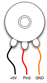
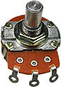
A potentiometer (pot for short) is an adjustable voltage divider whose range if connected as above is 0 to 5 volts. In fact this idea can work with any resistive device connected in a voltage divider configuration. This could include photocells and thermistors. For more on that see the following:
Connect the three LEDs as shown.
In the code below three LEDs (with 220 ohm dropping resistors) are connected in the "sink" configuration shown above. The program examines the value returned form the ADC and lights the corresponding LED based on that number. Use a 5K or 10K pot.
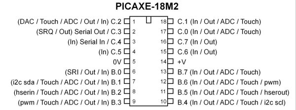
PICAXE 18M2.
The Program
symbol LED1 = C.2  ; to electrical pin 1
symbol LED2 = C.7  ; to electrical pin 16
symbol LED3 = C.6  ; to electrical pin 15
symbol val = b0  ; user variable
symbol wiper = C.1 ; where the pot wiper is connected

main: ; start program

readadc wiper, val  ; read 8-bit ADC value into variable val

   if val > 120 then top
   ; jump to label top if true
   if val > 70 AND val < 120 then middle
   ; jump to label middle if true
   if val < 70 then bottom
   ; jump to label bottom if true

goto main  ;jump back to the start


top:   ; label
HIGH LED1
LOW LED2
LOW LED3
goto main ; done jump back to start

middle:   ; label
LOW LED1
HIGH LED2
LOW LED3
goto main  ; done jump back to start

bottom:  ; label
LOW LED1
LOW LED2
HIGH LED3
goto main  ; done jump back to start
Picaxe Micro-controller Projects!
The PICAXE series of micro-controllers rank as the easiest and most cost effective way to use Microchip processors. I wanted an easier and less expensive way to introduce my students to the "PIC" micro-controller. Here I hope to get those starting out past poorly written literature and lack of simple working code examples.
- PICAXE Related videos Oct. 2016:
- Tutorial: Programming-Using PICAXE-18M2 Microcontroller
- How to setup PICAXE Pulse Width Modulation
- PICAXE TA8050P H-Bridge with Motor Control
- PICAXE TA8050P H-Bridge with Motor Speed Control
- PICAXE-18M2 Operates MOSFET H-Bridge
- PICAXE-18M2 Uses MCP23016 GPIO Expander
- Solar Panel Charge Controller Using PICAXE Microcontroller
- Exploring the PICAXE Micro-Controller
- Understanding Micro-Controller Input/Output Ports
- Using the 74HC165 Shift Register with the PICAXE Micro-Controller
- Connecting the 74HC595 Shift Register to PICAXE Micro-controller
- Using 7-Segment Displays with the PICAXE Micro-Controller
- Potentiometers and Analog-to-Digital Conversion with the PICAXE
- Pulse-Width Modulation Motor Speed Control and the PICAXE Micro-Controller
- Connecting the PICAXE to the DS1307 Real Time Clock
- Connecting the PICAXE to an External EEPROM (24LC08)
- Connecting a Servo to a PICAXE
- Connecting the TLC548 to the PICAXE
- Connecting the Ad5220 Digital Potentiometer to the PICAXE
See How I got into Electronics
