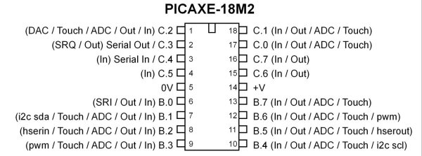
Fig. 1 PICAXE 18M2.
PICAXE 18M2 Microcontroller Operating 7-Segment Displays
This program uses a 74C164 shift register to count from 0 to F (HEX) on a 7 segment common anode LED display. This operates much the same was earlier demos using the 74HC164 to simply count in binary on a row of eight LEDs. The main objective is to explore code using several variations of the program. We'll also make use of the PICAXE internal EEPROM to store the segment code.
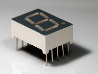
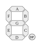
Fig. 2 typical 7-segment LED displays.
About LED Displays
A 7-segment LED display is simply a group of light emitting diodes arranged in the pattern of an eight (plus decimal point) that will display numbers when the appropriate are turned on.
Fig. 3 common anode configuration.
Fig. 3 three shows the LEDs connected in a common anode configuration where the anodes (positive electrode) are tied to a common connection. A common cathode LED display simply has the cathodes tied together in common and operate on the opposite electrical polarity. In this demo I used a common anode display where the common was tied to + 5 volts.
To use a common cathode display change the following line:
"if temp = 1 then LOW Bit_out else HIGH Bit_out endif" to
"if temp = 1 then HIGH Bit_out else LOW Bit_out endif" to invert the bit pattern. Tie the common to ground.
This program assumes a seven segment display with a bit pattern:
Q7 segment a
Q6 segment b
Q5 segment c
Q4 segment d
Q3 segment e
Q2 segment f
Q1 segment g
Q0 segment dp
Segment patterns 0 - 9, A - F Hex + dp are as follows:
0x3f, 0x06, 0x5b, 0x4f, 0x66, 0x6d, 0x7d, 0x07, 0x7f, 0x67, 0x77, 0x7c, 0x39, 0x5e, 0x79, 0x71, 0x80
Fig. 4 electrical connections to the 74HC164.
The electrical connections between the 74HC164 and the PICAXE 18M2 are as follows:
74HC164 pins 1, 2 (A-B) are connected to pin 15 (C.6) on the PICAXE;
74HC164 pin 8 (CP or CLK) is connected to pin 16 (C.7) on the PICAXE;
74HC164 pin 9 (MR) is connected to pin 1 (C.2) on the PICAXE.

Fig. 4
Program 1
The program below simply stores the segment code in use RAM then reads back the code in sequence where it's shifted into the register and displayed
#picaxe 18m2 ; type chip used

; set for 16 mHz clock
setfreq m16  ; All M2 - k31, k250, k500, m1, m2, m4, m8,m16,m32

; user variables
symbol val = b0
symbol temp = b1
symbol j =b2
symbol i = b3

; store display code in user RAM

poke 50,0x3f ;0 dec 63
poke 51,0x06 ;1 dec 6
poke 52,0x5b ;2 dec 91
poke 53,0x4f ;3 dec 79
poke 54,0x66 ;4 dec 102
poke 55,0x6d ;5 dec 109
poke 56,0x7d ;6 dec 125
poke 57,0x07 ;7 dec 7
poke 58,0x7f ;8 dec 127
poke 59,0x67 ;9 dec 103
poke 60,0x77 ;A dec 119
poke 61,0x7c ;b dec 124
poke 62,0x39 ;C dec 57
poke 63,0x5e ;d dec 94
poke 64,0x79 ;E dec 121
poke 65,0x71 ;F dec 113
poke 66,0x80 ;dp dec 128


symbol Bit_out = C.6
symbol CLK = C.7
symbol CLR = C.2

HIGH CLR ; must be set HIGH or 74HC164 won't operate
pulsout CLR,10 ; clear shift register

main:

for j = 50 to 65 ; location of 7-segment code

peek j, val

    ; routine has LSB out first

   for i = 0 to 7 ; begin bit-shift routine
     temp = val & %00000001 ;mask all bits except first
     if temp = 1 then LOW Bit_out else HIGH Bit_out endif
     pulsout CLK,1 ; clock bit into register
     val = val / 2 ; shift bits one place right
   next i ; end bit shift routine

   pause 2000 ; wait

next j

goto main
Fig. 5
Program 2
In this program we store the segment code within the EEPROM within the PICAXE instead of user RAM. The difference is the code is not lost when the power is turned off. Because the PICAXE compiler doesn't recognize HEX code when inputting data into the EEPROM, I had to convert it to decimal.
Another thing to note is the 256 bytes of EEPROM in the PICAXE- 18M2 occupies program flash memory address 1792 to 2048. This we lose program memory to the EEPROM.
; PICAXE- 18M2 Program memory 1792 up to 2048 is EEPROM 0 to 255

#picaxe 18m2 ; type chip used


EEPROM 0,(63,6,91,79,102,109,125,7,127,103,119,124,57,94,121,113)
; save segment values in EEPROM

; set for 16 mHz clock
setfreq m16
; All M2 - k31, k250, k500, m1, m2, m4, m8,m16,m32

; user variables
symbol val = b0
symbol temp = b1
symbol j =b2
symbol i = b3


symbol Bit_out = C.6
symbol CLK = C.7
symbol CLR = C.2

HIGH CLR ; must be set HIGH or 74HC164 won't operate
pulsout CLR,10 ; clear shift register

main:

for j = 0 to  15 ; location of 7-segment code

   read j,val  ;read value from EEPROM

    ; routine has LSB out first

   for i = 0 to 7 ; begin bit-shift routine
     temp = val & %00000001 ;mask all bits except first
     if temp = 1 then LOW Bit_out else HIGH Bit_out endif
     pulsout CLK,1 ; clock bit into register
     val = val / 2 ; shift bits one place right
   next i ; end bit shift routine

   pause 2000 ; wait

next j

goto main
Picaxe Micro-controller Projects!
The PICAXE series of micro-controllers rank as the easiest and most cost effective way to use Microchip processors. I wanted an easier and less expensive way to introduce my students to the "PIC" micro-controller. Here I hope to get those starting out past poorly written literature and lack of simple working code examples.
- PICAXE Related videos Oct. 2016:
- Tutorial: Programming-Using PICAXE-18M2 Microcontroller
- How to setup PICAXE Pulse Width Modulation
- PICAXE TA8050P H-Bridge with Motor Control
- PICAXE TA8050P H-Bridge with Motor Speed Control
- PICAXE-18M2 Operates MOSFET H-Bridge
- PICAXE-18M2 Uses MCP23016 GPIO Expander
- Solar Panel Charge Controller Using PICAXE Microcontroller
- Exploring the PICAXE Micro-Controller
- Understanding Micro-Controller Input/Output Ports
- Using the 74HC165 Shift Register with the PICAXE Micro-Controller
- Connecting the 74HC595 Shift Register to PICAXE Micro-controller
- Using 7-Segment Displays with the PICAXE Micro-Controller
- Potentiometers and Analog-to-Digital Conversion with the PICAXE
- Pulse-Width Modulation Motor Speed Control and the PICAXE Micro-Controller
- Connecting the PICAXE to the DS1307 Real Time Clock
- Connecting the PICAXE to an External EEPROM (24LC08)
- Connecting a Servo to a PICAXE
- Connecting the TLC548 to the PICAXE
- Connecting the Ad5220 Digital Potentiometer to the PICAXE
See How I got into Electronics
