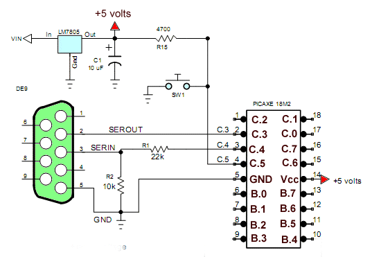
Fig. 1 Schematic to my home built test board minus I/O resistors.
PICAXE 18M2 Reading DS1307 Real Time Clock
This program does pretty much the same as my Arduino Ds1307 clock program does. It demonstrates the use of code and how to connect hardware. The program allows the user to input the time from the PICAXE terminal after Sw1 is pressed. For a detailed explanation of the Ds1307 see the following :
- Using the ATMEGA168/Arduino with a Ds1307 Real Time Clock
- ATMEGA168 Arduino Micro-Controller Projects
- Display Time/Date with Arduino, LCD Display, and Ds1307 RTC

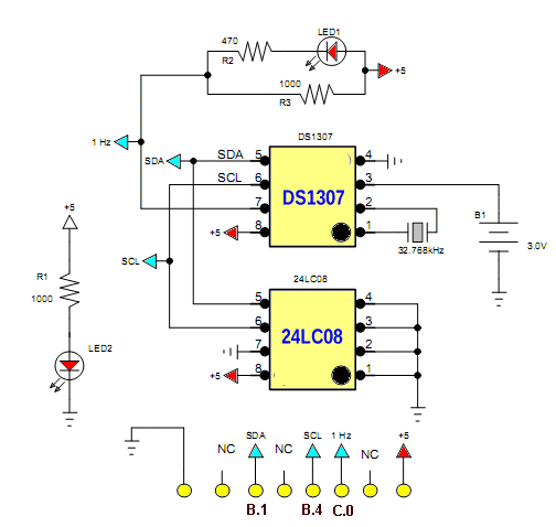
Fig. 2 Ds1307-24LC08 test board.
This is a module I constructed to combine an EEPROM and the Ds1307 RTC. One could just connect only the Ds1307 section by itself. Be sure to connect the 1 Hz out pin to C.0 on the PICAXE.

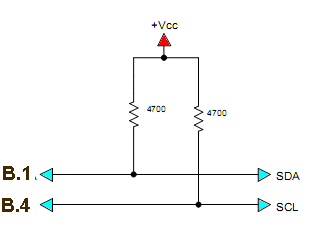
Fig. 3 These pullup resistors must be connected between the PICAXE and Ds1307 module.
These 4.7k pullup resistors must be connected as shown between the module in Fig. 2 and the PICAXE.
; Use a Ds1307 RTC
#picaxe 18m2 ; type chip used


symbol Sw1 = pinC.5 ; use pinX.X for input
symbol LED1 = C.7
symbol LED2 = C.6
symbol val = b13  ; if needed
symbol temp = b14


symbol oneHZ = pinC.0 ; connect to Ds1307 1 Hz out


symbol seconds = b0
symbol mins = b1
symbol hour = b2
symbol day = b3
symbol date = b4
symbol month = b5
symbol year = b7
symbol control = b8


hi2csetup i2cmaster, %11010000, i2cslow, i2cbyte ; Ds1307 setup

main:

if Sw1 = 0   then set_clock

if oneHz = 0 then goto main ; wait here for a HIGH from 1 Hz


hi2cin 0,(seconds,mins,hour,day,date,month,year)


; ASCII code 48 -> 57 is 0 -> 9 so add/subtract 48
; order is sec - min - hours - day - month - year
; could also use bcdtoaschii (p. 35) but this illustrates the process.

sertxd("The time is: ")

; print hours

val = hour / 16 + 48
; shift high nibble 4 places right change to ASCII
sertxd(val)
val = hour & %000001111 + 48
; mask high nibble change lower nibble to ASCII
sertxd(val, ":")

; print minutes

val = mins /16 + 48
; shift high nibble 4 places right change to ASCII
sertxd(val)
val = mins & %00001111 + 48
; mask high nibble change lower nibble to ASCII
sertxd(val, ":")

; print seconds

val = seconds / 16 + 48
; shift high nibble 4 places right change to ASCII
sertxd(val)
val = seconds & %00001111 + 48
; mask high nibble change lower nibble to ASCII
sertxd(val, 13, 10) ; LF - CR


pause 600

goto main


set_clock: ; input time to Ds1307

; use programming cable

HIGH LED1

sertxd("Input time HH:MM:  ")

disconnect ; must use to input string from programming cable.

for bptr = 28 to 38 ;

serrxd [2000],@bptr

sertxd(@bptr) ; echo input

if @bptr = 10 then EXIT  ; break loop on LF-CR

next bptr

reconnect ; reactivate programming cable.

sertxd(13,10) ; LF-CR

; translate 4 ASCII to two digits of BCD
; doesn't seem to work with @bptr

peek 28,val
temp = val - 48 * 16 & %00110000 ; upper nibble hour
if temp > 0x20 then gosub zero_temp
peek 29,val
val = val - 48 & %00001111  ; lower nibble hour
if val > 0x09 then gosub add6
hour = temp | val
;skip 30
peek 31,val
temp = val - 48 * 16 & %11110000
if temp > 0x50 then gosub zero_temp
peek 32,val
val = val - 48 & %00001111
if val > 0x09 then gosub add6
mins = temp | val


let seconds = $00; 00 Note all BCD format
;let mins    = $41; 59 Note all BCD format
;let hour    = $10; 11 Note all BCD format
let day     = $05; Note all BCD format
let date    = $21; 25 Note all BCD format
let month   = $12; 12 Note all BCD format
let year    = $11; 03 Note all BCD format
let control = %00010000 ; Enable output at 1Hz
hi2cout 0,(seconds,mins,hour,day,date,month,year,control)

pause 1000

LOW LED1

goto main


zero_temp:

temp = 0
return

add6:

val = val + 6
return
Picaxe Micro-controller Projects!
The PICAXE series of micro-controllers rank as the easiest and most cost effective way to use Microchip processors. I wanted an easier and less expensive way to introduce my students to the "PIC" micro-controller. Here I hope to get those starting out past poorly written literature and lack of simple working code examples.
- PICAXE Related videos Oct. 2016:
- Tutorial: Programming-Using PICAXE-18M2 Microcontroller
- How to setup PICAXE Pulse Width Modulation
- PICAXE TA8050P H-Bridge with Motor Control
- PICAXE TA8050P H-Bridge with Motor Speed Control
- PICAXE-18M2 Operates MOSFET H-Bridge
- PICAXE-18M2 Uses MCP23016 GPIO Expander
- Solar Panel Charge Controller Using PICAXE Microcontroller
- Exploring the PICAXE Micro-Controller
- Understanding Micro-Controller Input/Output Ports
- Using the 74HC165 Shift Register with the PICAXE Micro-Controller
- Connecting the 74HC595 Shift Register to PICAXE Micro-controller
- Using 7-Segment Displays with the PICAXE Micro-Controller
- Potentiometers and Analog-to-Digital Conversion with the PICAXE
- Pulse-Width Modulation Motor Speed Control and the PICAXE Micro-Controller
- Connecting the PICAXE to the DS1307 Real Time Clock
- Connecting the PICAXE to an External EEPROM (24LC08)
- Connecting a Servo to a PICAXE
- Connecting the TLC548 to the PICAXE
- Connecting the Ad5220 Digital Potentiometer to the PICAXE
See How I got into Electronics
