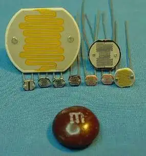
Various CdS Photocells
Using a CdS Photoresistor-Photocell
by Lewis Loflin
A cadmium-sulfide (CdS) photo resistor (or photo cell) is a device that changes resistance depending on light intensity. It's sensitive, fast, and has been around for decades. It's often used in street lights and as an "electric eye."
Note the resistance decreases from millions of ohms in darkness to as little as a few hundred ohms in bright light. A simple test is to use an ohm meter and watch the resistance vary with light intensity.
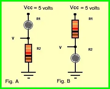
In the above circuit (Fig. A) R1 is a CdS photocell in series with a 1000-ohm resistor. The 5 volts form VCC divides across R1 and R2 in proportion to their resistance.
For example, if R1 = R2, one would read 2.5 volts across each component. Using a DC voltmeter (black lead on ground, red lead at V) one will read 2.5 volts. (Or whatever value depending on the particular CdS cell and light intensity.)
Connecting the voltmeter across the CdS cell (black lead to V and red at Vcc) one will read 2.5 volts. If the meter leads are reversed, say red to ground and black to V, the voltage reading will be negative 2.5 volts with a digital meter.
Note: the voltage across R1 plus the voltage across R2 when added together will equal Vcc. This is a property of series circuits where each component have the same current flow through them, but voltage divides based on resistance.
As we increase the light intensity to R1 the voltage across R2 will increase while the voltage across R1 decreases. This is because the resistance of R1 decreases with light intensity while the resistance of R2 is fixed.
Voltage divides based on resistance where the higher resistance gets more of the voltage drop. As in the previous case, the voltage across R1 plus the voltage across R2 will still add back to Vcc. In figure B above we have the opposite voltage reading because the parts are reversed.
The voltage from ground to V will decrease as light intensity increases.
The output at V can be used with an analog to digital converter of a microcomputer to measure light intensity. Let's look at more another application.
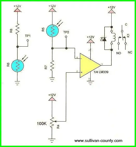
Using a Comparator with a CdS
Pictured above is the Lm339 quad comparator operating a relay. When the voltage at the "-" input (pin 5) exceeds the voltage at the "+" input (pin 6) the output (internal) open-collector transistor at pin 2 switches on to ground, activating the relay K1. (D4 is used to protect the Lm339 from voltage spikes generated by K1 when deactivated.
As light intensity increases the resistance of R5 decreases the voltage will rise across R7 until the voltage at Tp2 exceeds the voltage set by R4, activating the relay.
If we use R6 and R8, the relay when activate as it gets dark. For more on comparators see vc.htm. For the same circuit as above using a uA741 OP-AMP see cir1.jpg.
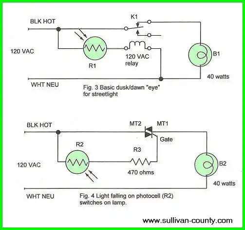
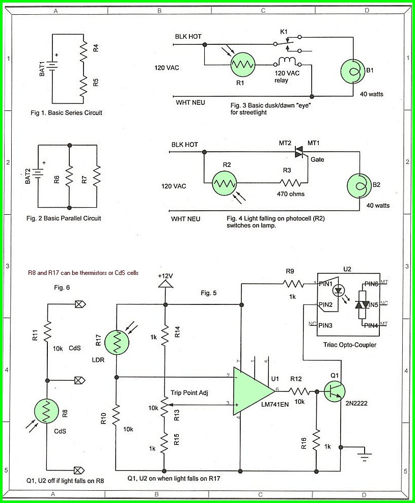
In Fig. 3 above the CdS cell is used in series with a 120 VAC relay. During the day the resistance of the CdS cell is low activating the relay and breaking the connection to the lamp. At night increased resistance deactivates the relay. The diagram shows the state of the circuit at night.
In Fig. 4 as the resistance of the CdS drops current is supplied to the gate of the Triac turning on the lamp. See my triacs page.
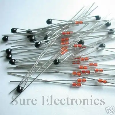
Thermistors I purchased off Ebay
Thermistor
A thermistor is a type of resistor with resistance varying according to its temperature. The word is a combination of thermal and resistor. Samuel Ruben invented the thermistor in 1930. This differs from a mechanical thermostat that uses metals expansion/contraction to break a contact.
If the resistance increases, we say it has a positive coefficient. If decreases, a negative coefficient. They are not used alone, but with other electronics. Thermistors can be used in the same circuits as CdS cells. A thermistor is not to be confused with a thermocouple or thermostat.
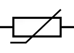
Thermistor symbol
Such resistive devices should be used with a constant current sources for accuracy.
- Constant Current Circuits with LM317, LM334, etc.
- Experiments with TL431 Shunt Regulator
- LM334 CCS Circuits with Thermistors, Photocells
- LM317 Constant Current Source Circuits
- Photo Detector Devices:
- Photodiode Circuits Operation and Uses
- Photodiode Op-Amp Circuits Tutorial
- Photo Voltaic Tutorial MOSFET Output Solid State Relays
- Transistor Driver Circuits
- Opto-Isolated Transistor Drivers for Micro-Controllers
- MOSFET Transistors, IGBTs Observations
![]()
- Quick navigation of this website:
- You Tube Channel
- Basic Electronics Learning and Projects
- Basic Solid State Component Projects
- Arduino Microcontroller Projects
- Raspberry Pi Electronics, Programming
- ULN2003A Darlington Transistor Array with Circuit Examples
- Tutorial Using TIP120 and TIP125 Power Darlington Transistors
- Driving 2N3055-MJ2955 Power Transistors with Darlington Transistors
- Understanding Bipolar Transistor Switches
- N-Channel Power MOSFET Switching Tutorial
- P-Channel Power MOSFET Switch Tutorial
- More Power MOSFET H-Bridge Circuit Examples
- Build a High Power Transistor H-Bridge Motor Control
Web site Copyright Lewis Loflin, All rights reserved.
If using this material on another site, please provide a link back to my site.