Load Lamp Safely Allows Safer Electronic Testing
First and foremost read this safety warning. This is at your own risk and for information purposes only.
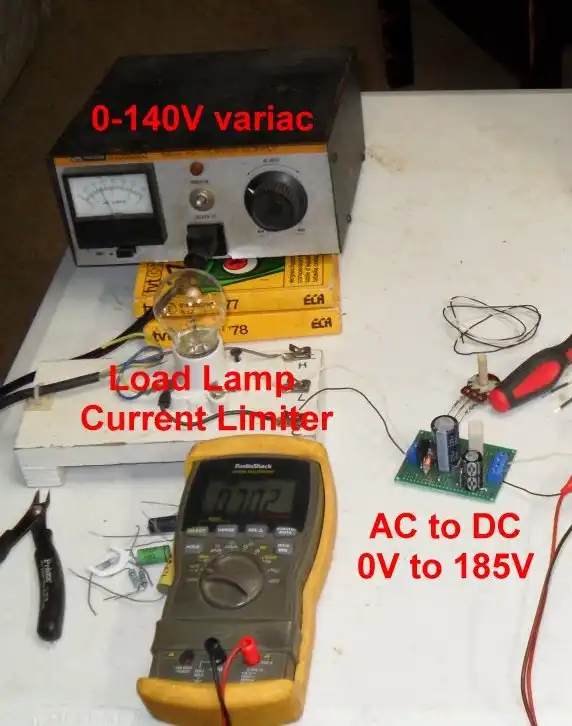
Also see Build Autotransformer-Variac AC and DC Power Supply.
A load lamp is simply a common light bulb in series with a device being tested. My purpose here is to give a more detailed account of how to use it. Here we will learn how to determine what wattage light bulb to use and what to expect when something is working right versus something being wrong. Let's look at and discuss some real world examples.
Fig. 1 shows how the lamp is connected. Assuming 120VAC and a standard 3-prong electrical cord. The 'HOT' (black) would go to an on/off switch, which then connects to whatever is being tested. The GRN - WHT wires (neutral and ground) connect together and form the common connected to the 'white' or shiny metal screw on the lamp base.
The item being tested is then connected to the brass screw side of the lamp socket and the switch (points A and B). If one had an isolation transformer between the plug in and power I'd highly suggest using it.
How this works is an incandescent light bulb filament has a low resistance when cold, typically under 20 ohms. When current begins to flow and filament heats up and resistance rises rapidly to act as a sort of current safety valve.
If the item being tested, in this illustration a transformer, has any shorts or draws excessive current the energy is absorbed by the lamp and doesn't cause further damage to the device or blow expensive fuses.
The transformer could even be connected backwards and would still be protected while the lamp glows nice and bright. Note: higher watt lamps have lower filament resistance than low watt lamps!
To determine what wattage bulb to use the check the power rating of the device to be checked. A 100-watt light bulb operates at a current of .84 Amps. If for example a VCR is rated at 30 watts that's .25 Amps.
In general I like to keep the lamp current versus in this case the VCR current at a ratio of at least 3 to one. A 75-watt or 100-watt bulb would be fine.
Also consider that the VCR in this example is simply powered on and not running a tape. There will be little current from the power supply inside the VCR being used. This "idle" current is very low and the lamp will be dim at best.
Hit 'play' and watch a movie the lamp will glow some, that is normal. If the bulb is bright after replacing say a blown fuse, then the likely problem most of the time is a short or problem in the switching power supply.
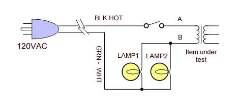
Fig. 2 (above) shows how to obtain higher wattage and current. Say whatever we're testing is 65 watts. That's a line current of 65/120 = .51 Amps. Three times what would require close to a 200-watt lamp. (200/120 = 1.67 Amps.)
If one has a 150-watt or 200-watt lamp this is fine, but we could parallel two 100-watt or two 75-watt lamps and do the same thing. Let's look at some real world examples. Be your own judge.
Considering Transformers and Reactance
First go read my two webpages on transformers:
Let's say for example I have a Radio Shack transformer rated at 12.VAC at 3 Amps. The transformer at no load (secondary disconnected) is rated at 140 mA max (.14 Amp.) idle current. If I used as 15-watt bulb (125 mA) and assuming the transformer current was 100 mA, the bulb would half on. A 100 watt bulb would be dark. This is normal. If the 100 watt bulb was glowing even dimly, that could be a problem.
Let's go to another example. In class we had several large power transformers. When connected to a 40-watt bulb they glowed with a reddish light. The transformer winding measured very few ohms so most of the current was reactive. No power was being used even though we had a current flow.
Reactive power is what is found in large values of inductance and capacitance. To test this take a 8uF or 10uF 200VAC non-polarized capacitor and connect it to 120VAC. (These are the types used as motor start capacitors.)
Put an ammeter in series and note the current flow. No power is being used because the power absorbed by the cap during the charge cycle is fed back to the source during the discharge cycle.
The cap will never gets hot and does nothing. This is an example of apparent power rated in volt-amps (VA). For more on this my videos:
In the case of the large transformers this was mostly reactive power producing the current that dimly lite the bulb. This is normal. If it's a small transformer with some ohmic resistance and the filament on a larger bulb glowed that is likely a problem such as some shorted windings or just a crappy transformer that will get hot.
Real World Example
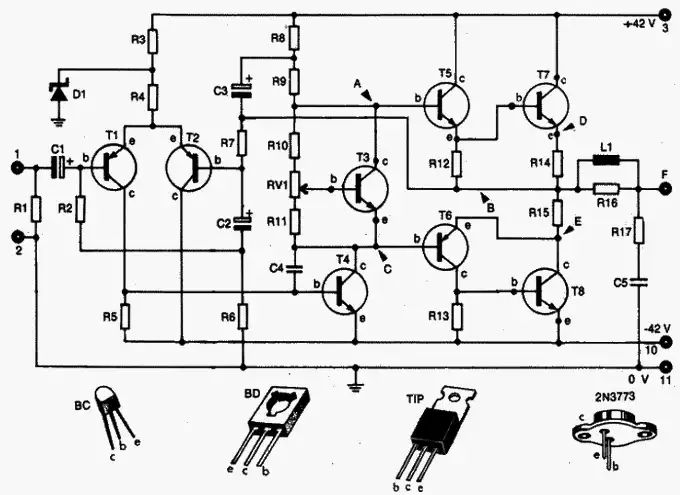
One visitor to the site had a problem with an audio amplifier kit he ordered and this is where using a load lamp will save the day. In fig. 3 we have a sample direct-coupled audio amplifier.
What that means is one transistor is connected directly to the next and if any one fails, usually multiple transistors will be knocked out. Replace one or two but miss number three, then powered up the two new ones will like be damaged.
The load lamp blocks the over-current and prevents damage until all of the problems are fixed.
The first thing I had him check was if the bi-polar power supply was working. In this case it's plus and minus 45 volts and a common ground. If working correctly point B in the schematic would read close to zero volts. If this was a single polarity amplifier then point B would be half the power supply voltage.

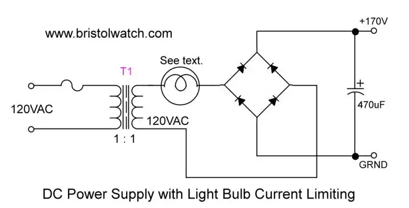
With the load lamp attached (100-watt bulb) he found his negative side of the bi-polar supply missing. Fig. 4 (above) is the power supply he built and it was wired wrong. He rewired the supply and the amp started working.
With no audio input the bulb glowed dimly and the power supply was reading 35 volts on each polarity. That is normal because the voltage drop due to idle current was consumed by the lamp. Remove load lamp 45 volts returns and the problem solved.

Fig. 5 (above) is an example of a switching power supply. These are used in almost everything today replacing expensive and bulky transformers. As one can see even this simple unit we have scores of small parts that like the audio amp above are direct coupled. Any bad part will likely destroy others even if several are replaced, the new ones could be toast.
The best way to trouble shoot this is disconnect whatever it's powering up and try the load lamp. See if the 15 volts (or whatever) is there. If it is then the problem could be whatever the unit supplies power to.
I hope this clarified the video.
See Load Lamp for Safe Electrical Testing video
New, updated for August 2021:
- Quick navigation of this website:
- Basic Electronics Learning and Projects
- Basic Solid State Component Projects
- Arduino Microcontroller Projects
- Raspberry Pi Electronics, Programming
- Load Lamp Safely Allows Safer Electronic Testing
- How to use SIDACs and Their Operation
- Build Autotransformer-Variac AC and DC Power Supply
- Warning About Electrical Shock and How to Prevent It
- YouTube
- SIDAC Controlled Flashtube and Pulse Circuits
- Build Autotransformer-Variac AC and DC Power Supply
- Build Autotransformer-Variac AC and DC Power Supply
- Understanding Unijunction Transistors Theory Operation
- Unijunction Transistor SCR Photo Flash Control Circuit
- Arduino Measures Current from Constant Current Source
- Constant Current Source Theory Testing
- Review Ohm's Law for Trouble-Shooting CCS Circuits
- Arduino Power Magnetic Driver Board for Stepper Motors
- Arduino Controlled Power Constant Current Source
- Theory and Operation of Capacitors
Related video to above:
- Constant Current Source Multimeter Trouble Shooting
- Ohm's Law Review for Constant Current Source
- Arduino Unipolar Stepper Motor Driver Board with Arduino Code
- Arduino Controlled Constant Current Source
Other Circuits
- Coils for Highly Selective Crystal Radio
- Neon (NE-2) Circuits You Can Build
- Understanding Xenon Flashtubes and Circuits
Web site Copyright Lewis Loflin, All rights reserved.
If using this material on another site, please provide a link back to my site.