Fig. 1
Warning About Electrical Shock
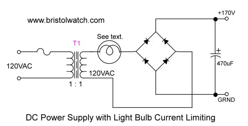
Fig. 1 uses a light bulb as a current limiter and isolation transformer to prevent electrical shock from a "HOT" ground, etc. This is an example.
- Load Lamp Safely Allows Safer Electronic Testing
- Build Autotransformer-Variac AC and DC Power Supply
Some of these experiments could produce injury or death. Don't conduct any of these experiments unless qualified to do so. If under 18, proceed only under adult supervision!
The information contained in this website is for general information purposes only. I endeavor to keep the information up to date and correct. The experiments presented on this website were conducted in a college classroom under strict instructor supervision. Any reliance you place on such information is therefore strictly at your own risk.
Most of the experiments presented use 5, 12, or 24 volts D.C. and should be safe. 24V AC-DC or 48V AC-DC should be OK.
For those using over 120 or 220 volts I recommend the following be used in the classroom:
1. Use an isolation transformer. In the case of 220 and higher voltage use a step down transformers to 120 volts.
2. Place a 40 or 25 watt incandescent bulb in series with the experiment. The will limit the current in case of a short. Be extra careful with polarized capacitors because they can explode even under voltage if connected backwards or to A.C.
The primary factor for the severity of electric shock is the electric current which passes through the body, in particular the heart. This current is of course dependent upon the voltage and the resistance of the path it follows through the body. An approximate general framework for shock effects is as follows:
To put this in everyday terms, 1 mA is .001 Amp. A 100 watt light bulb draws 100 watts divided by 120 volt equals .840 Amps or 840 mA. The current from a 25 watt bulb (.208 A 208 mA) can kill you under the right circumstances.
Also note the issue of "hot chassis" when connecting test equipment to a test circuit as shown in images below. These relates to the B&K model 1653 test equipment.
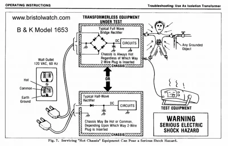
Fig. 2
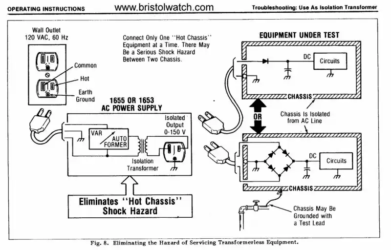
Fig. 3
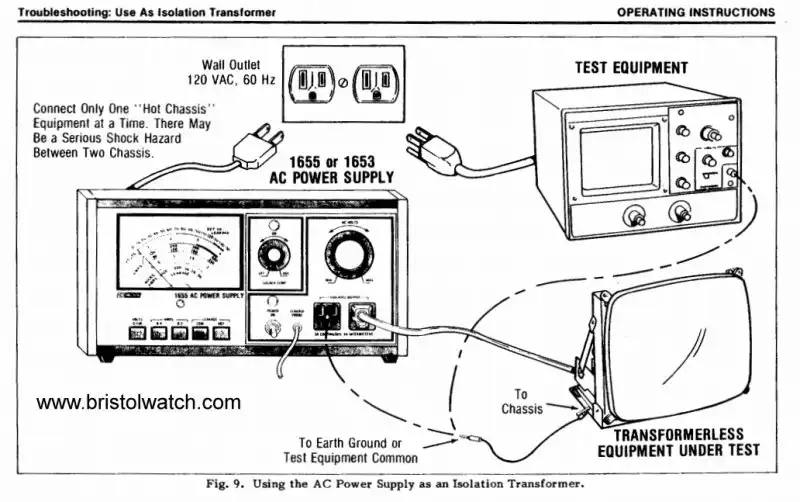
Fig. 4
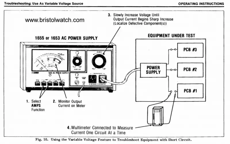
Fig. 5
- Quick navigation of this website:
- Basic Electronics Learning and Projects
- Basic Solid State Component Projects
- Arduino Microcontroller Projects
- Raspberry Pi Electronics, Programming
- Coils for Highly Selective Crystal Radio
- Neon (NE-2) Circuits You Can Build
- Understanding Xenon Flashtubes and Circuits
- Transistor circuits:
- ULN2003A Darlington Transistor Array with Circuit Examples
- Tutorial Using TIP120 and TIP125 Power Darlington Transistors
- Driving 2N3055-MJ2955 Power Transistors
- Understanding Bipolar Transistor Switches
- N-Channel Power MOSFET Switching Tutorial
- P-Channel Power MOSFET Switch Tutorial
- More Power MOSFET H-Bridge Circuit Examples
- Build a High Power Transistor H-Bridge Motor Control
- MOSFET-Transistor Drivers with TC4420 and TC4429, IGBTs, etc.
- Introduction TC4420-TC4429 MOSFET Drivers
- Use TC4420 MOSFET Driver for Simple H-Bridge Circuit
- TC4420 MOSFET Driver Various Circuits
- TC4420 MOSFET Driver Replacement Circuits
- Test Power MOSFET Transistors, IGBTs
- Insulated Gate Bipolar Transistor IGBT Circuits
- Issues on Connecting MOSFETs in Parallel
New, updated for August 2021:
- Load Lamp Safely Allows Safer Electronic Testing
- How to use SIDACs and Their Operation
- Build Autotransformer-Variac AC and DC Power Supply
- Warning About Electrical Shock and How to Prevent It
- YouTube
- SIDAC Controlled Flashtube and Pulse Circuits
- Build Autotransformer-Variac AC and DC Power Supply
- Build Autotransformer-Variac AC and DC Power Supply
- Understanding Unijunction Transistors Theory Operation
- Unijunction Transistor SCR Photo Flash Control Circuit
- Arduino Measures Current from Constant Current Source
- Constant Current Source Theory Testing
- Review Ohm's Law for Trouble-Shooting CCS Circuits
- Arduino Power Magnetic Driver Board for Stepper Motors
- Arduino Controlled Power Constant Current Source
- Theory and Operation of Capacitors
Related video to above:
- Constant Current Source Multimeter Trouble Shooting
- Ohm's Law Review for Constant Current Source
- Arduino Unipolar Stepper Motor Driver Board with Arduino Code
- Arduino Controlled Constant Current Source
Web site Copyright Lewis Loflin, All rights reserved.
If using this material on another site, please provide a link back to my site.