Fig. 1
Introduction Hall Effect Switches Sensors Circuits Tutorial
A Hall sensor in its most basic form is an analog integrated circuit. It consists of a Hall plate that outputs a "transverse" voltage based on the intensity of a magnetic field - polarity is dependant on magnetic polarity.
It also consists of a high gain differential amplifier because the generated voltage is small. The output voltage is analog usually centered around half the power supply voltage.
These are known as linear or ratiometric sensors.
The addition of a Schmitt trigger with a properly set hysteresis will create a Hall switch or Hall latch. They often have an open collector output transistor.
The Schmitt triggers used here are based on an analog comparator. These can be built from operational amplifiers (op-amps) such as the LM358 or LM741.
Or one can use the LM311 or LM339 quad comparator. The have open collector outputs unlike the LM311/LM741.
Often considered "digital" at this point we have in reality a one-bit analog-to-digital converter.
- Comparator Theory Circuits Tutorial
- Comparator Hysteresis and Schmitt Triggers
- Voltage Comparator Information And Circuits
- Looking at Window Comparator Circuits
Hall effect sensors are solid state magnetic sensor devices used as either magnetic switches or to measure magnetic fields. There are three basic types I'm concerned with here: The Hall effect switch, the Hall effect latch, and the ratiometric or analog output sensor.
Here I'm concerned with illustrating various electronic circuits and how to connect the sensors and use them.
A Hall effect switch will turn on in the presence of south magnetic field on its face or north magnetic field on the opposite side. It will turn off when the magnet is removed.
A Hall effect latch works like a switch, but will stay on when the magnet is removed. It will turn off if the north pole is applied to the face or the power is turned off. Below I have the schematic on how to use a Hall switch to make a single pole on/off switch.
A ratiometric Hall effect sensor outputs an analog voltage proportional to the magnetic field intensity. The devices I will use on a separate page are unipolar and in general with no magnetic field applied the output is one-half the supply voltage. The voltage will increase with the south magnetic pole on the face or decrease with the north magnetic pole on the face.
See Using Ratiometric Hall Effect Sensors
Here we will cover switches and latches that start as ratiometric then add comparators, Schmitt triggers, and output transistors. List below are the specification sheets for the Hall sensors used in my You Tube video.
Spec sheet listed below.
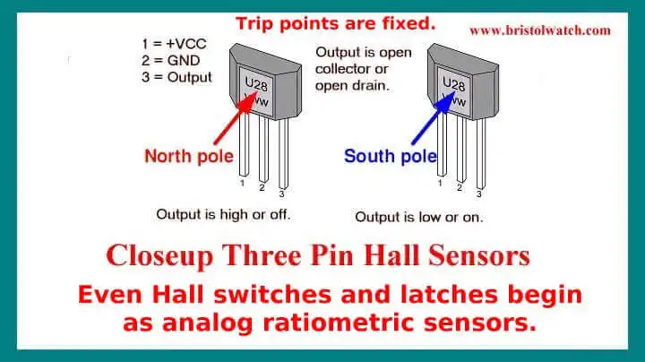
Pictured above are typical pin outs on Hall sensors. The south pole of the magnet goes towards the 'face' turning the device on. The north pole on the face will have no effect unless the device is a latch, which it will turn off if it's already on.
Let's consider a UGN3013T five volt Hall effect switch. To trip the switch on requires typically 500 gauss to a max of 750 gauss. But to release or cut off is a typical 225 gauss to as low as 110 gauss.
So we have a reasonable range of 275 that we need to stay in for reliable operation. So it's obvious even a small iron magnet may work well or has to be very close to the sensor.
Note this is an old obsolete part I just happened to have. Newer units are much more sensitive.
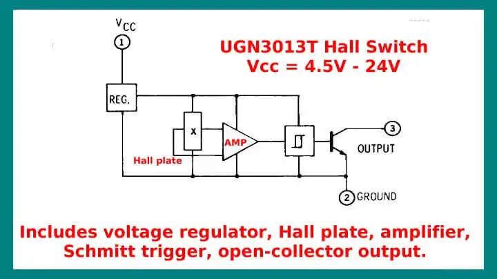
Fig. 2
Pictured above is the internal block diagram of a Hall effect switch in this case a UGN3013T. It includes the Hall plate, an amplifier, Schmitt trigger, and open collector transistor output. Some may use a an open drain MOSFET instead of a bipolar transistor.
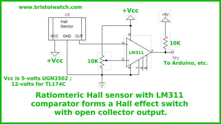
Fig. 3
Ratiometric Hall sensor with LM311 comparator forms a Hall effect switch with open collector output form a switch with an adjustable trigger point. Vcc is 5-volts if using sensor such as UGN3502 and 12-volts for a TL174C. This can be directly connected to the input port of a micro-controller or other 5-volt digital logic.
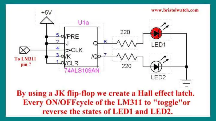
Fig. 4
By adding a JK flip-flop to our Hall effect switch in Fig. 3 we form a Hall effect latch. The state of Q and QNOT "flip" with every ON-OFF cycle at TP2.
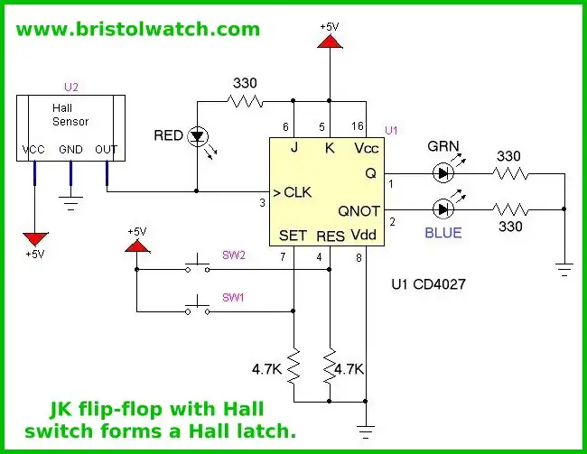
Fig. 5
Fig. 5 show how to use a Hall switch with open-collector/drain output with a CD4027 JK flip-flop to form a latch circuit.
This completes our introduction to Hall effect sensors and circuits.
- YouTube videos:
- Basic Hall Effect Sensors YouTube
- Hall Effect Sensor Circuits YouTube
- Basics of Hall Effect Analog Sensors & Switches Pt. 1
- Operate, Build Hall Effect Switch Pt. 2
- Hall Effect Latches Theory and Circuits Pt. 3
- Hall Sensor Circuits, Theory, Operation Updated 2022
- How Hall Effect Sensors Detect Ferrous Metals
- Exploring Omni Hall Effect Sensors with the TI DRV5032
- LM311 Comparator Projects Using Hall Sensors
- Hall Sensor with Alternating Current
- Using Hall Effect Switches and Sensors
- Using Ratiometric Hall Effect Sensors
- Hall Effect Sensors with the Arduino
- Spec. sheets all PDF formate:
- UGN3013 Hall Switch (PDF file)
- TL173C 12-Volt Ratiometric Hall Sensor
- UGN3503 5-Volt Ratiometric Hall Effect Sensor
- Honeywell SS466 Hall Latch
Web site Copyright Lewis Loflin, All rights reserved.
If using this material on another site, please provide a link back to my site.