Fig. 1
LM311 Comparator Projects for Hobbyists Using Hall Sensors
by Lewis Loflin
Review of ratiometric Hall Sensors. Also called linear Hall sensors.
Click above for larger image in new tab.
Also see Hall Sensor Circuits, Theory, Operation
With a ratiometric sensor the output or VOUT increases/decreases depending on magnet strength, polarity, and distance from the Hall device.
With no magnetic field present VOUT = measures a little over 50% of +Vcc supply voltage. As the south pole approaches the printed face VOUT increases. I've never seen any sensor go to full VCC.
The north pole of the magnet on the printed side decreases VOUT all the way to zero if strong enough.
Note the non-printed face also works the same but opposite. The north pole increases VOUT.
Note: 1 Tesla = 1000 mT; 1 mT = 10 gauss. A strong refrigerator magnet is ~100 gauss or 10 mT. An MRI machine magnet is 1-3 Tesla.
Hall switches and latches are considered digital devices. They add a Schmitt trigger circuit and an open collector output transistor.
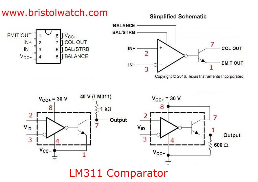
Fig. 2
Click above for larger image in new tab.
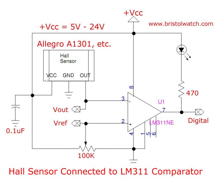
In Fig. 1 I used a ratiometric Hall sensor with an LM311 comparator.
The LM311 comparator has an open collector output. (Fig. 2) The transistor turns on when VOUT of the Hall sensor is greater than VREF. This turns on the LED.
Caution: check the Hall sensor maximum voltage ratings on the spec sheet! Most ratiometric Hall sensors operate at 4.5-volts to 6-volts.
I used 12V for VCC so VOUT is 6-volts with no magnetic input. I set VREF for 7-volts. A magnet (south pole at printed face) increases VOUT to greater than 7-volts the LM311 comparator switches on, LED turns on.
Remove the magnet the comparator/LED turn off at 7-volts.
But what happens if the Hall output stays at 7-volts? This can create instability or even oscillation.
What we want is separate on and off points - hysteresis. We want differing switch on and switch off points.
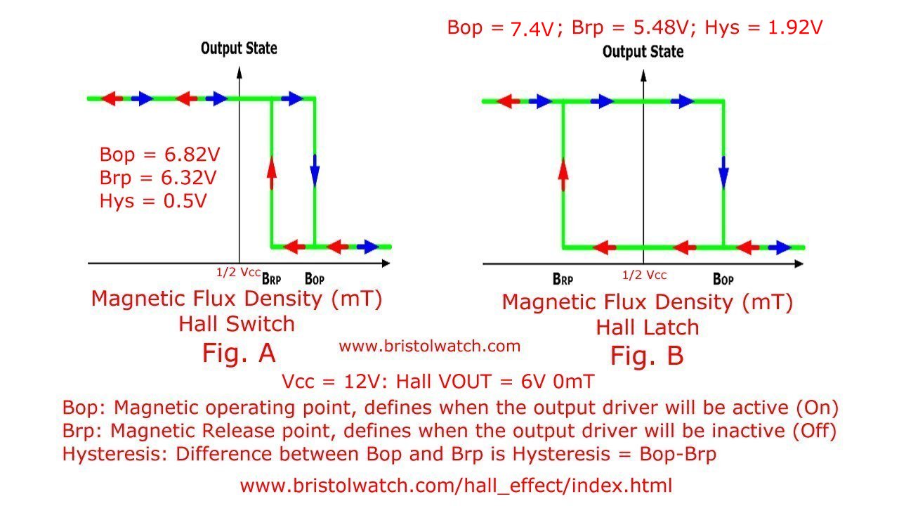
Fig. 3 Hysteresis voltage points Hall switch versus Hall latch.
Click above for larger image.
Also see Hysteresis Voltage Level Hall Latch
The following is taken from Melexis Engineering edited by me.
Referring to Fig. 3 consider "Output State" as being 6-volts from my analog Hall sensor at 12-volts.
Terminology:
Bop: Magnetic operating point, defines when the output driver will be active (On)
Brp: Magnetic Release point, defines when the output driver will be inactive (Off)
Hysteresis: Difference between Bop and Brp is Hysteresis = Bop-Brp
Refer to Fig. 3 left side.
The Bop and Brp point are both above 6-volts. When the ratiometric Hall sensor exceeds Bop the output transistor turns on, turns the LED on.
When the Hall sensor VOUT drops below Brp the LED urns off.
To quote:
"Unipolar switch - Only active in one spectrum (North or South) , typically used for position sensing. Bop and Brp will be enabled with the same magnetic pole. A minimum hysteresis is required to avoid unwanted togglings (oscillation) coming from magnet or mechanical variations."
As Fig. 1 is constructed there is no hysteresis. Assuming VREF is 7-volts and VOUT is 7-volts the circuit is unstable.
Proper operation for example the comparator should switch on at say 7.5-volts, but switch off at 6.5-volts. Bop - Brp = 1-volt.
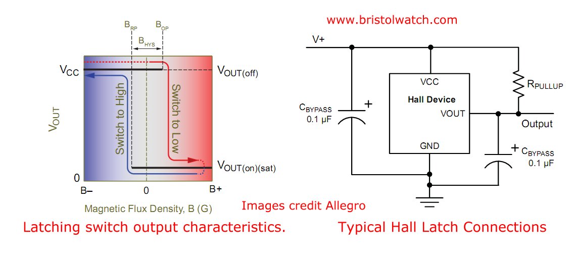
Latch also called Bipolar switch - Is activated with one magnetic field and deactivated with the opposite magnetic field.
The operating point and the release point are having the same absolute values but are opposite from sign. Bop = - Brp.
Both thresholds are symmetrical centered around 0mT or ~6V.
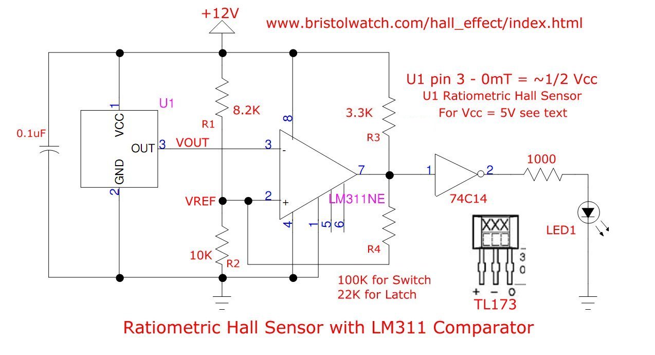
Fig. 4 Click above for larger image in new tab.
A Hall Switch
LM311 Comparator pin connections.
In Fig. 4 I have connected the output (VOUT) to an LM311 comparator. I have introduced hysteresis into the circuit with resistor R4. It sets VREF to one voltage when the comparator is off, to a differing voltage when on.
This is called Schmitt trigger.
Let's start with a switch.
Refer to:
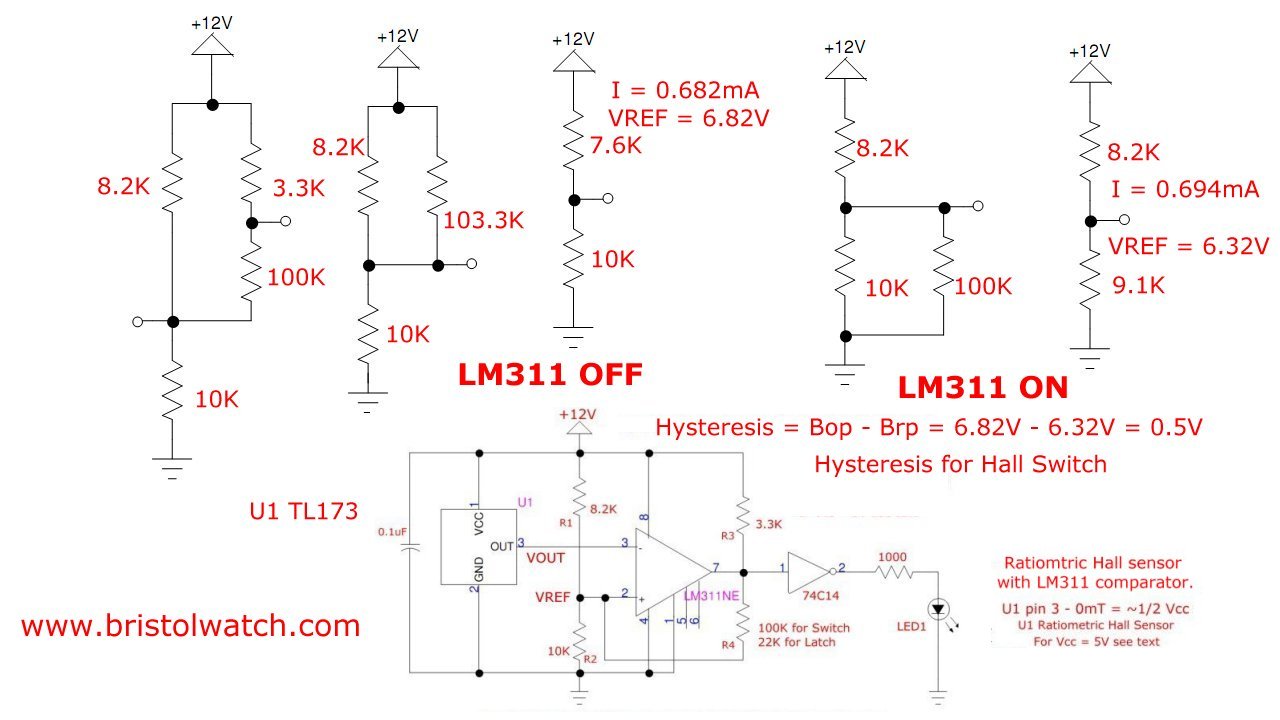
Let's work out this problem for the LM311 turned off or VREF > VOUT from the Hall sensor.
R3 (3.3K) and R4 (100K) are in series: 3.3K + 100K = 103.3K, I'll designate RS.
R1 (8.2K) is in parallel with RS (103.3K). Using the parallel resistance formula: RPS = (R1 * RS) / (R1 + RS) = 7.6K.
R2 (10K) is in series with RPS: 10K + 7.6K = 17.6k.
Divide +Vcc (12V) by 17.6K = 0.682mA. VREF = 10K * 0.682mA = 6.82V. This is called Bop.
Once Again Terminology:
Bop: Magnetic operating point, defines when the output driver will be active (On)
Brp: Magnetic Release point, defines when the output driver will be inactive (Off)
Hysteresis: Difference between Bop and Brp is Hysteresis = Bop-Brp
The Hall sensor only puts out 6V so the LM311 and LED are off until Bop is reached.
South pole of a magnet will increase VOUT depending on distance from the printed face.
When VOUT = 6.82V the LM311 pin 7 goes low, LED is turned on through the 74C14.
When the LM311 turns on VREF will change. R4 (100K) is now in parallel with R2 (10K)
RP = (100K * 10K) / (100K + 10K) = 9.1K.
RP (9.1K) is in series with R2 (8.2K): 9.1K + 8.2K = 17.3K.
+Vcc (12V) / 17.3K = 694uA.
VREF = 9.1K * 694uA = 6.32V. This is Brp.
The LED turns off when VOUT < Brp when the magnet is removed from the sensor.
Hysteresis = Bop - Brp = 6.82V - 6.32V = 0.5V
Here we created a Hall switch because VOUT at 0mT (no magnet) at ~6V is less than Brp.
See Comparator Hysteresis and Schmitt Triggers
A Hall Latch
Refer to the following:
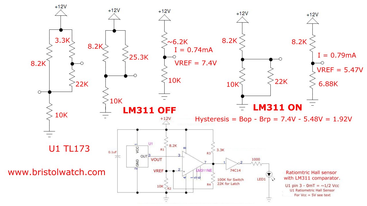
Now I'll turn to building a Hall latch. All components are the same except R4 goes from 100K to 22K.
With the LM311 turned off R4 (22K) is in series with pull up resistor R3 (3.3K): RS = 22K + 3.3K = 25.3K.
RS (25.3K is in parallel with R1 (8.2K): RSP = (25.3K * 8.2K) / ( 25.3K + 8.2K) = ~6.2K.
RSP (6.2K) and R2 (10K) are in series: 6.2K + 10K = 16.2K.
+Vcc (12V) / 16.2K = 0.74mA. Multiply by R2 to get VREF: 0.74mA * 10K = 7.4V.
Thus Bop = 7.4V.
Now we calculate Brp for our latch.
With the LM311 turned on R2 (10K) is in parallel with R4 (22K).
RP = (10K * 22K) / (10K + 22K) = 6.88K.
RP (6.88K) is in series with R1 (8.2K): 6.89K + 8.2K = 15.1K
+Vcc (12V) / 15.1K = 0.79mA; Brp = 6.89K * 0.79mA = ~5.47V
When the south pole of a magnet approaches the printed face of the Hall sensor, the output increases. At 7.4V the LM311 and LED turn on.
Remove the magnet VOUT falls back to ~6V. This is above Brp, the LM311/LED remain on.
Reverse magnet polarity to north approach the Hall sensor printed face. VOUT decreases. When VOUT drops to Brp the LM311/LED turn off.
Hysteresis = Bop - Brp = 7.4V - 5.48V = 1.92V.
See Hysteresis Hall Switch versus Hall Latch.
![]()
- Hysteresis Voltage Level Hall Latch
- Hysteresis Hall Switch Calculations
- Hysteresis Hall Latch Calculations
- Comparator Circuits:
- Comparator Theory Circuits Tutorial
- Comparator Hysteresis and Schmitt Triggers
- Voltage Comparator Information And Circuits
- Looking at Window Comparator Circuits
- Photodiode Circuits Operation and Uses
- Photodiode Op-Amp Circuits Tutorial
- YouTube:
- Photodiodes and How they Work
- Photodiode Op-Amp Circuits
- Using Photovoltaic MOSFET Drivers
- YouTube:
- Comparator Circuits Introduction
- Hall Sensor Circuits, Theory, Operation Updated 2022
- How Hall Effect Sensors Detect Ferrous Metals
- Exploring Omni Hall Effect Sensors with the TI DRV5032
- LM311 Comparator Projects Using Hall Sensors
- Hall Sensor with Alternating Current
- Using Hall Effect Switches and Sensors
- Using Ratiometric Hall Effect Sensors
- Hall Effect Sensors with the Arduino
- YouTube videos:
- Basic Hall Effect Sensors YouTube
- Hall Effect Sensor Circuits YouTube
- Basics of Hall Effect Analog Sensors & Switches Pt. 1
- Operate, Build Hall Effect Switch Pt. 2
- Hall Effect Latches Theory and Circuits Pt. 3
- Quick navigation of this website:
- Basic Electronics Learning and Projects
- Basic Solid State Component Projects
- Arduino Microcontroller Projects
- Raspberry Pi Electronics, Programming
Web site Copyright Lewis Loflin, All rights reserved.
If using this material on another site, please provide a link back to my site.