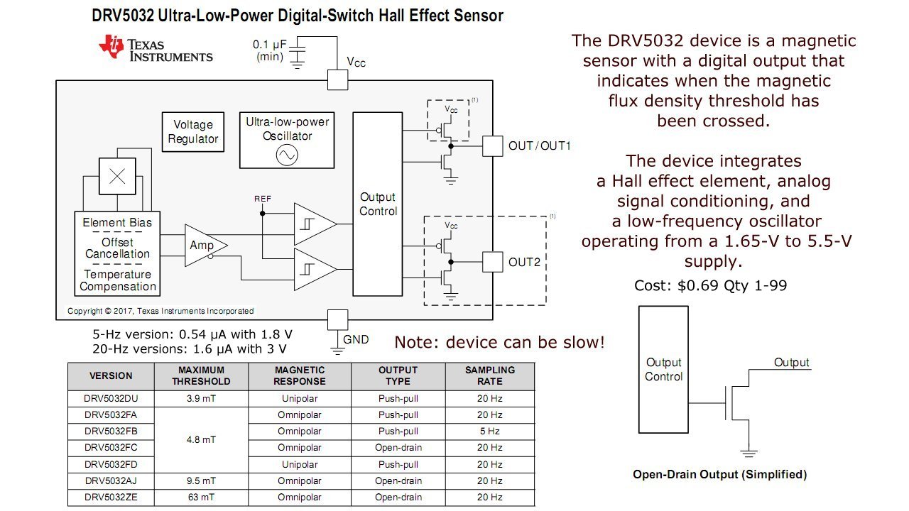
Fig. 1 DRV5032 Hall sensor internal block diagram.
Click image for greater detail.
Exploring Omni Hall Effect Sensors with the TI DRV5032
by Lewis Loflin
Note the DRV5032 block diagram in Fig. 1.
An omni Hall effect switch has two operate-release points that depend on the magnetic polarity of a magnet. In this case I'll use the Texas Instruments DRV5032.
These are mostly 4-pin devices: ground, +VCC, and two outputs labeled OUT1/OUT or OUT2. It operates at 1.65 to 5.6 volts.
It has either open drain output or push-pull outputs. See the illustration DRV5032 Features.
Fig. 1A Operation of Omni Hall Effect Switch.
Image courtesy Sensor Solutions.
They are very low power due to an on board oscillator running at 5Hz. or 20Hz. The device is "asleep" most of the time. To quote the specification sheet:
The DRV5032 device is a magnetic sensor with a digital output that indicates when the magnetic flux density threshold has been crossed. The device integrates a Hall effect element, analog signal conditioning, and a low-frequency oscillator that enables ultra-low average power consumption. By operating from a 1.65-V to 5.5-V supply, the device periodically measures magnetic flux density, updates the output, and enters a low-power sleep state.
The uses they list are:
Battery-critical position sensing
Electricity meter tamper detection
Cell Phone, laptop, or tablet case sensing
E-locks, smoke detectors, appliances
Medical devices, IoT systems
Valve or solenoid position detection
Contactless diagnostics or activation.
This device is slow, but great for contactless switches or proximity sensors. They are useless for higher speed applications such as detecting motor shaft rotation speed.
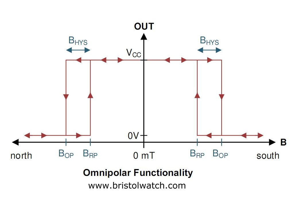
Fig. 2 DRV5032 Hall sensor operate and release points.
Click image for greater detail.
This device has two switch on/off points with hysteresis. This shown in Fig. 2.
This differs from a Hall switch that is active only with the south pole operating on the left side of Fig. 2
This also differs from a Hall latch that stays on until the north pole of the magnet drives the Hall plate voltage to a point below 0mT.
The omni Hall effect operates as a typical Hall switch with the south pole on the printed face. It turns off as the magnet is removed. This I think is OUT2.
If the magnetic polarity is reversed (north on the printed face) OUT1 turns on. It turns off as the magnet is removed.
Referring to Fig. 1 this is accomplished by using dual Schmitt triggers.
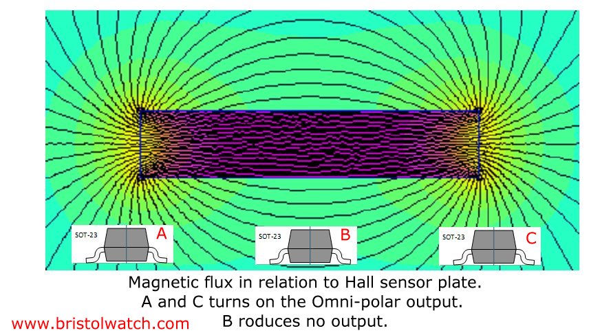
Fig. 3 Magnetic flux in relation to Hall sensor operation.
Click image for greater detail.
In Fig. 3 note the relation of magnetic flux from a bar magnet in relation to a Hall sensor. The Hall plate is assumed to be parallel to the printed face.
When the magnetic flux is perpendicular to the "printed face" (A and C) the device will operate. If the flux is parallel to the Hall plate (B) the outputs remain inactive.
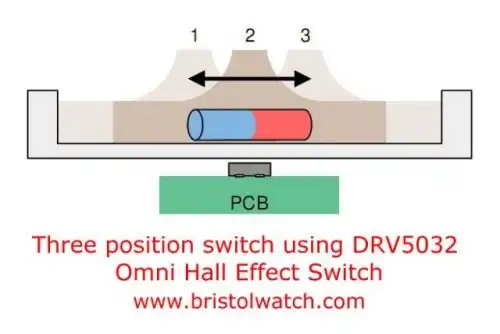
Fig. 4 Three position no-contact switch based on DRV5032 Hall sensor.
This can be used to create a no contact single-pole, double-throw switch as shown in Fig. 4.
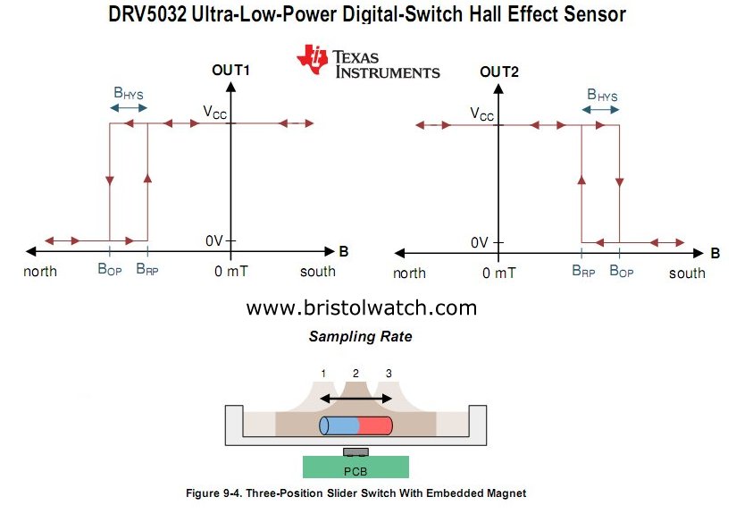
Fig. 5 DRV5032 Hall sensor operate and release points.
Click image for greater detail.
Fig. 5 illustrates the switch points (BOP, BRP) based on position of a magnet. Center position both outputs are off.
- YouTube videos:
- Basic Hall Effect Sensors YouTube
- Hall Effect Sensor Circuits YouTube
- Basics of Hall Effect Analog Sensors & Switches Pt. 1
- Operate, Build Hall Effect Switch Pt. 2
- Hall Effect Latches Theory and Circuits Pt. 3
Hall Sensors
A Hall sensor in its most basic form is an analog integrated circuit. It consists of a Hall plate that outputs a "transverse" voltage based on the intensity of a magnetic field - polarity is dependant on magnetic polarity.
It also consists of a high gain differential amplifier because the generated voltage is small. The output voltage is analog usually centered around half the power supply voltage.
The addition of a Schmitt trigger with a properly set hysteresis will create a Hall switch or Hall latch. They often have an open collector output transistor.
The Schmitt triggers used here are based on an analog comparator. These can be built from operational amplifiers (op-amps) such as the LM358 or LM741.
Or one can use the LM311 comparator or LM339 quad comparator. The have open collector outputs unlike the LM311/LM741 op-amps.
A comparator "compares" two analog voltages and turns on-off based on their voltage levels.
Often considered "digital" at this point we have in reality a one-bit analog-to-digital converter.
![]()
- Hall Sensor Circuits, Theory, Operation Updated 2022
- How Hall Effect Sensors Detect Ferrous Metals
- Exploring Omni Hall Effect Sensors with the TI DRV5032
- LM311 Comparator Projects Using Hall Sensors
- Hall Sensor with Alternating Current
- Using Hall Effect Switches and Sensors
- Using Ratiometric Hall Effect Sensors
- Hall Effect Sensors with the Arduino
- Quick navigation of this website:
- Basic Electronics Learning and Projects
- Basic Solid State Component Projects
- Arduino Microcontroller Projects
- Raspberry Pi Electronics, Programming
- Comparator Circuits:
- Comparator Theory Circuits Tutorial
- Comparator Hysteresis and Schmitt Triggers
- Voltage Comparator Information And Circuits
- Looking at Window Comparator Circuits
- Photodiode Circuits Operation and Uses
- Photodiode Op-Amp Circuits Tutorial
- YouTube:
- Photodiodes and How they Work
- Photodiode Op-Amp Circuits
- Using Photovoltaic MOSFET Drivers
- Comparator Circuits Introduction
Web site Copyright Lewis Loflin, All rights reserved.
If using this material on another site, please provide a link back to my site.