Fig. 1 Small magnet on back of Hall sensor is used detect ferrous metal.
Click image for greater detail.
How Hall Effect Sensors Detect Ferrous Metals
by Lewis Loflin
Adding a small magnet to the back of a Hall-sensor allows detection of ferrous metal, or its absence.
I will explain theory of operation and build a working prototype Hall-sensor circuit.
"Ferrous" as used here refers to iron, steel, and various alloys. If it can be magnetized, its presence or absence can de detected.
This is based on using a ratiometric (analog out) Hall-sensor often combined with a property designed Schmitt trigger. In this demonstration I use an LM311 comparator.
To understand the operation of an analog Hall-sensor see Hall Sensor Circuits, Theory, Operation.
Or one can see the brief review of Hall-sensors below.
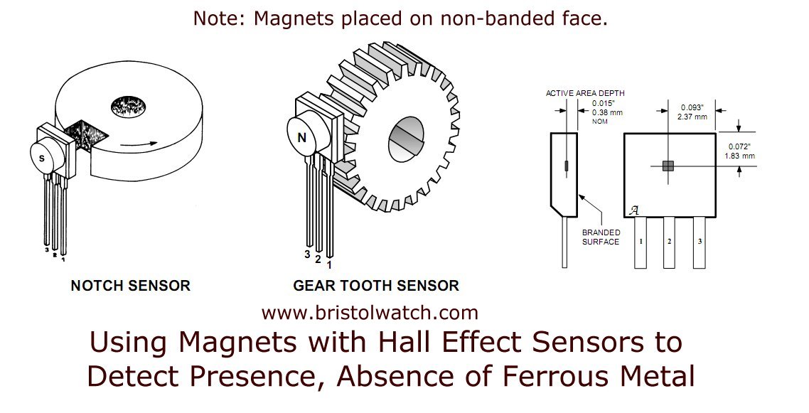
Note in Fig. 1 the bias magnet is mounted on the non-printed side of the Hall-sensor.
Fig. 2 Hall sensor detects ferrous metal, rejects non-ferrous metals brass, aluminum.
Fig. 2 illustrates the operation of a commercial Hall-sensor detecting the presence of steel bolts. It ignores the aluminum bar, the brass bolt, and the steel bolt too far away from the sensor.
The sensor includes an integrated "bias" magnet whose magnetic field creates a small induced magnet in the object to be detected.
Image courtesy of Sensor Solutions.

Fig. 3 Hall-sensor integrated unit detects steel gear teeth.
Fig. 3 illustrates the internal construction of a commercial Hall-sensor used to detect teeth in a steel gear.
The gap must be noted - if the gap is too wide the magnetic field from the bias magnet inside the sensor housing can't induce magnetism in the gear tooth.
That is why one steel bolt from Fig. 2 was not detected - the gap was too large.
Fig. 4
Fig. 4 illustrates voltage output from a analog Hall-sensor is proportion to flux intensity and magnetic polarity.
The internal high-gain differential amplifier is biased at one-half the power supply voltage with zero magnetic flux. This point I label Q.
In Fig. 4 the sensor has a 5-volt supply so the Q point is ~2.5V.
Image courtesy of Sensor Solutions.
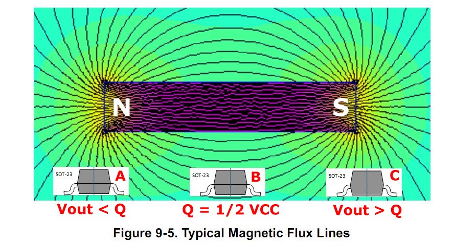
Fig. 5 Flux from bar magnet in relation to Hall-sensor operation.
Click image for greater detail.
Fig. 5 illustrates the magnetic flux from a typical bar magnet in relation to three Hall-sensors.
Sensor A is influenced by negative flux (north pole) and the output voltage drops below Q towards zero.
Sensor B output is at Q because the magnetic flux is parallel to the internal Hall plate. The flux must be perpendicular to the Hall "plate". That is the case with sensors A and C.
Sensor C is influenced by positive flux (south pole) and the output voltage increases towards +VCC the power supply voltage.
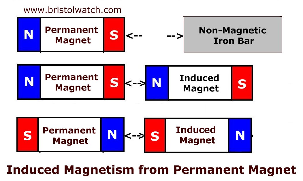
Fig. 6
Click image for greater detail.
Permanent magnet creates an induced magnet from non-magnetized ferrous metal.
The magnetic polarity of the induced magnet is directly related to the polarity of the permanent magnet.
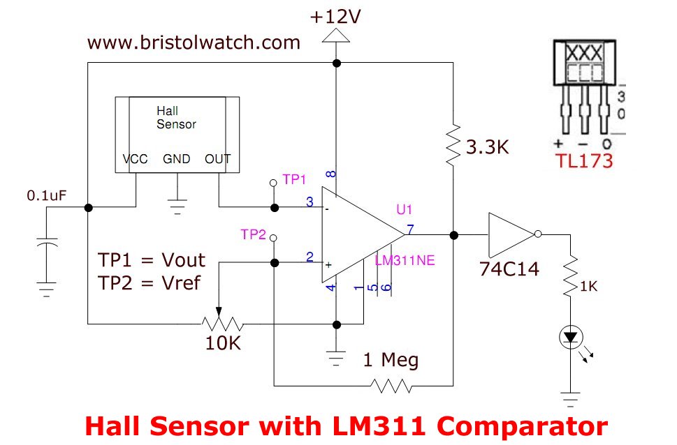
Fig. 7
Click image for greater detail.
Fig. 7 is my prototyped test circuit. It consists of a ratiometric (analog output) Hall-sensor, an LM311 comparator used as a Schmitt trigger, and a 10K potentiometer to adjust the reference voltage.
The output drives an indicator LED through a 74C14 inverter.
When VOUT (TP1) exceeds VREF (TP2) the LED will turn on.
My power supply voltage is 12V.
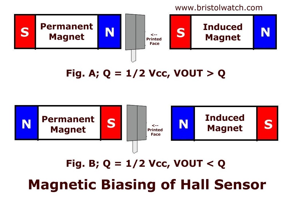
Fig. 8
Click image for greater detail.
How induced magnetism in ferrous metal operates a Hall-sensor.
In Fig. 8A a permanent magnet north pole is placed on the back side (non-printed side) of the Hall-sensor. The output voltage increases above Q (6V) towards 12V.
Adjust the 10K potentiometer so the reference voltage output until output LED just turns off. This is just above the output voltage from the sensor.
An iron bar is placed on the printed side of the sensor into the magnetic field of the permanent magnet.
The new induced south pole on the printed face further increases the voltage. The voltage will now be greater than VREF and the LED will turn on. The metal has been detected.
Pull the metal away the LED will go off.
In Fig. 8B a permanent magnet south pole is placed on the back side (non-printed side) of the Hall-sensor. The output voltage decreases below Q (6V) towards 0V.
An iron bar is placed on the printed side of the sensor into the magnetic field of the permanent magnet.
The new induced north pole on the printed face further decreases the output voltage VOUT towards 0V.
Adjust the 10K potentiometer reference voltage where the output LED just turns off. This is just above the VOUT voltage.
Pull the metal away the LED will turn on. VOUT will increase above VREF turning on the LED. We detected an absence of metal.
The remaining four slides display the measured voltages.
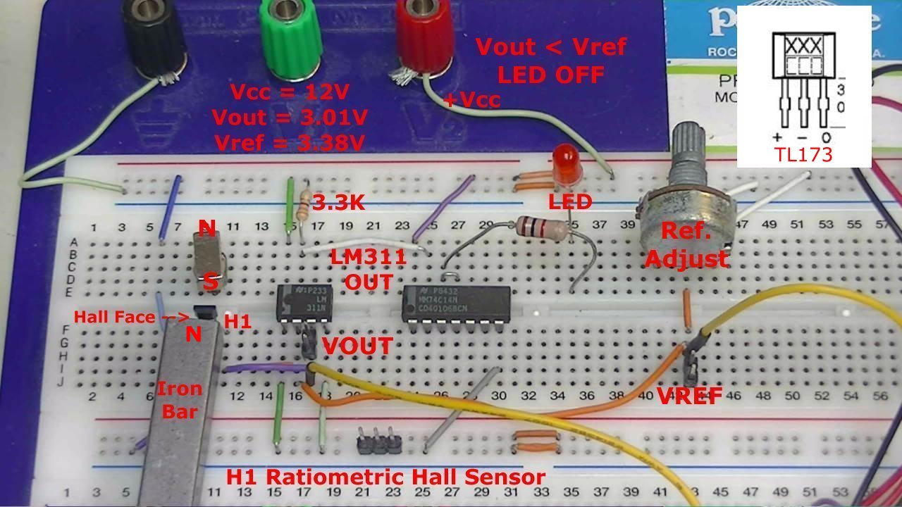
Fig. 9
Click image for greater detail.
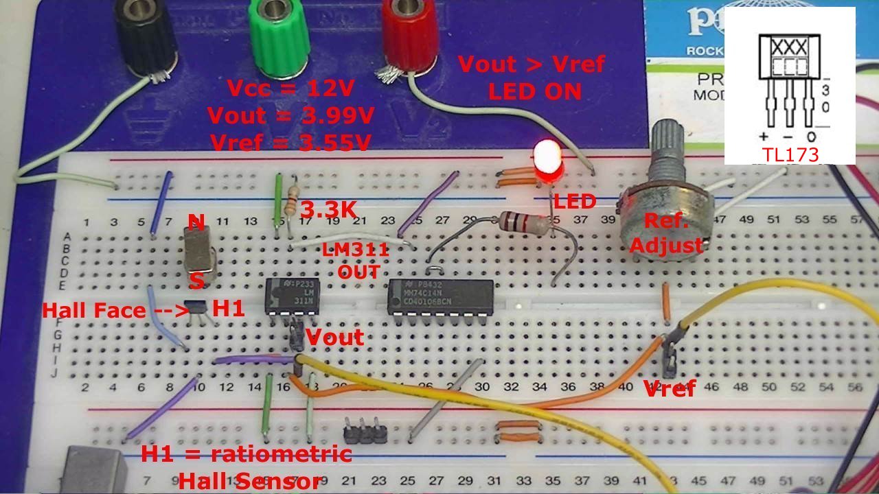
Fig. 10
Click image for greater detail.
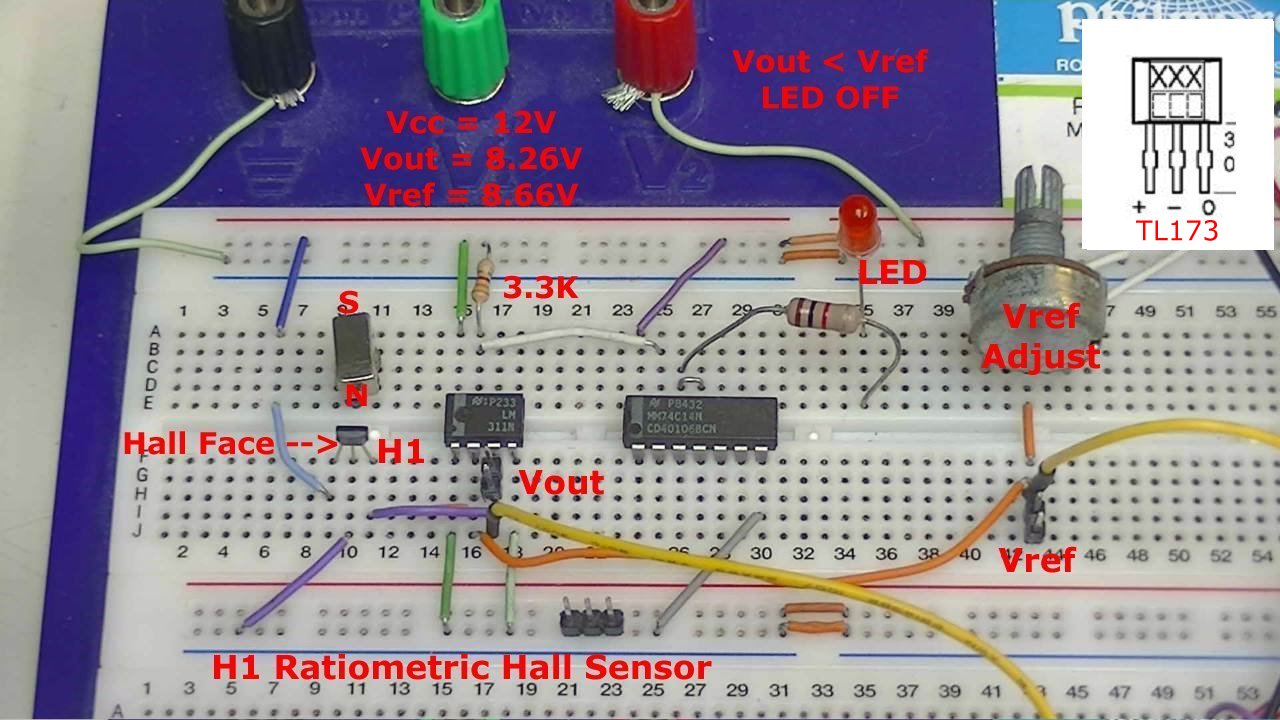
Fig. 11
Click image for greater detail.
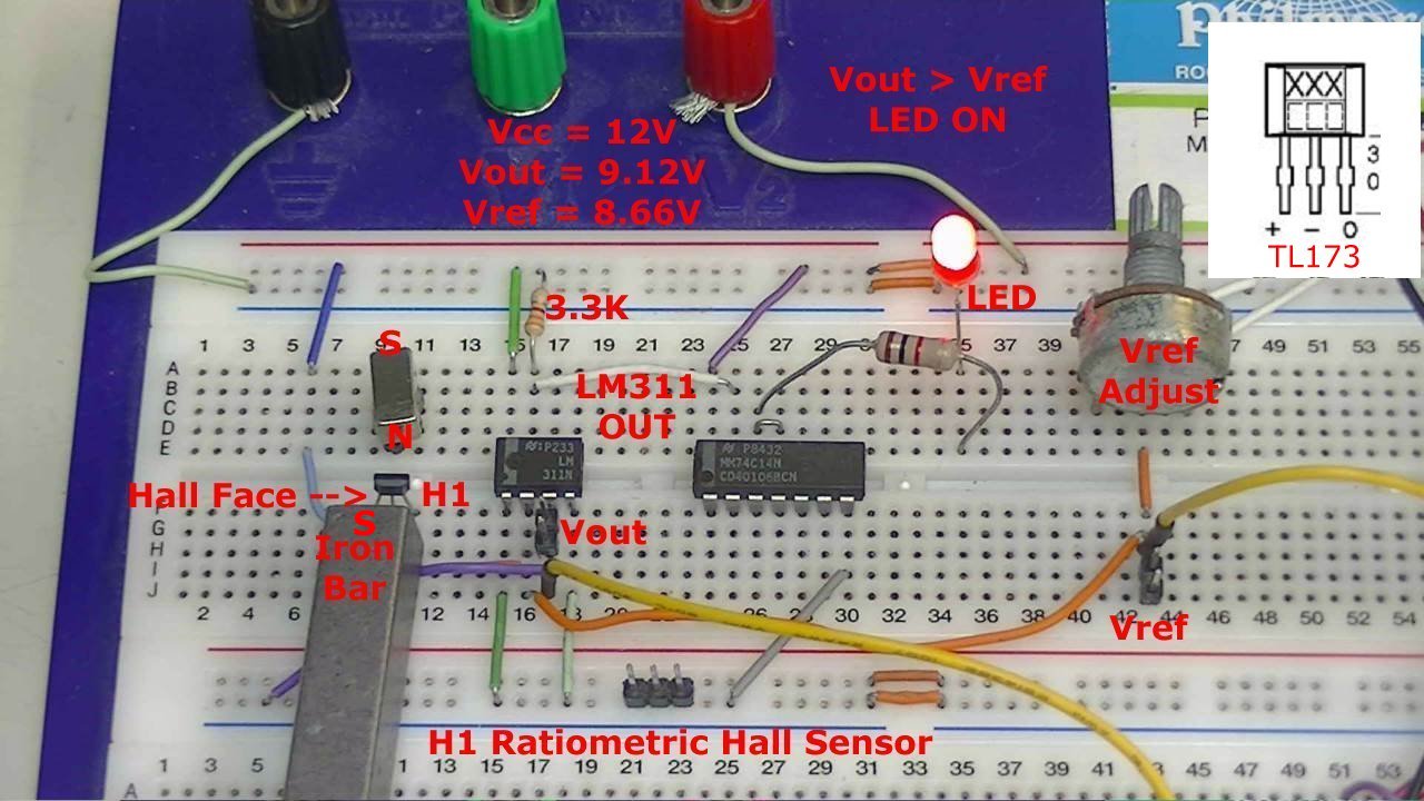
Fig. 12
Click image for greater detail.
Hall Sensors
A Hall sensor in its most basic form is an analog integrated circuit. It consists of a Hall plate that outputs a "transverse" voltage based on the intensity of a magnetic field - polarity is dependant on magnetic polarity.
It also consists of a high gain differential amplifier because the generated voltage is small. The output voltage is analog usually centered around half the power supply voltage.
The addition of a Schmitt trigger with a properly set hysteresis will create a Hall switch or Hall latch. They often have an open collector output transistor.
The Schmitt triggers used here are based on an analog comparator. These can be built from operational amplifiers (op-amps) such as the LM358 or LM741.
Or one can use the LM311 comparator or LM339 quad comparator. The have open collector outputs unlike the LM311/LM741 op-amps.
A comparator "compares" two analog voltages and turns on-off based on their voltage levels.
Often considered "digital" at this point we have in reality a one-bit analog-to-digital converter.
![]()
- Hall Sensor Circuits, Theory, Operation Updated 2022
- How Hall Effect Sensors Detect Ferrous Metals
- Exploring Omni Hall Effect Sensors with the TI DRV5032
- LM311 Comparator Projects Using Hall Sensors
- Hall Sensor with Alternating Current
- Using Hall Effect Switches and Sensors
- Using Ratiometric Hall Effect Sensors
- Hall Effect Sensors with the Arduino
- YouTube Hall Effect Videos
- Basic Hall Effect Sensors YouTube
- Hall Effect Sensor Circuits YouTube
- Quick navigation of this website:
- Basic Electronics Learning and Projects
- Basic Solid State Component Projects
- Arduino Microcontroller Projects
- Raspberry Pi Electronics, Programming
- Comparator Circuits:
- Comparator Theory Circuits Tutorial
- Comparator Hysteresis and Schmitt Triggers
- Voltage Comparator Information And Circuits
- Looking at Window Comparator Circuits
- Photodiode Circuits Operation and Uses
- Photodiode Op-Amp Circuits Tutorial
- YouTube:
- Photodiodes and How they Work
- Photodiode Op-Amp Circuits
- Using Photovoltaic MOSFET Drivers
- YouTube:
- Comparator Circuits Introduction
Web site Copyright Lewis Loflin, All rights reserved.
If using this material on another site, please provide a link back to my site.