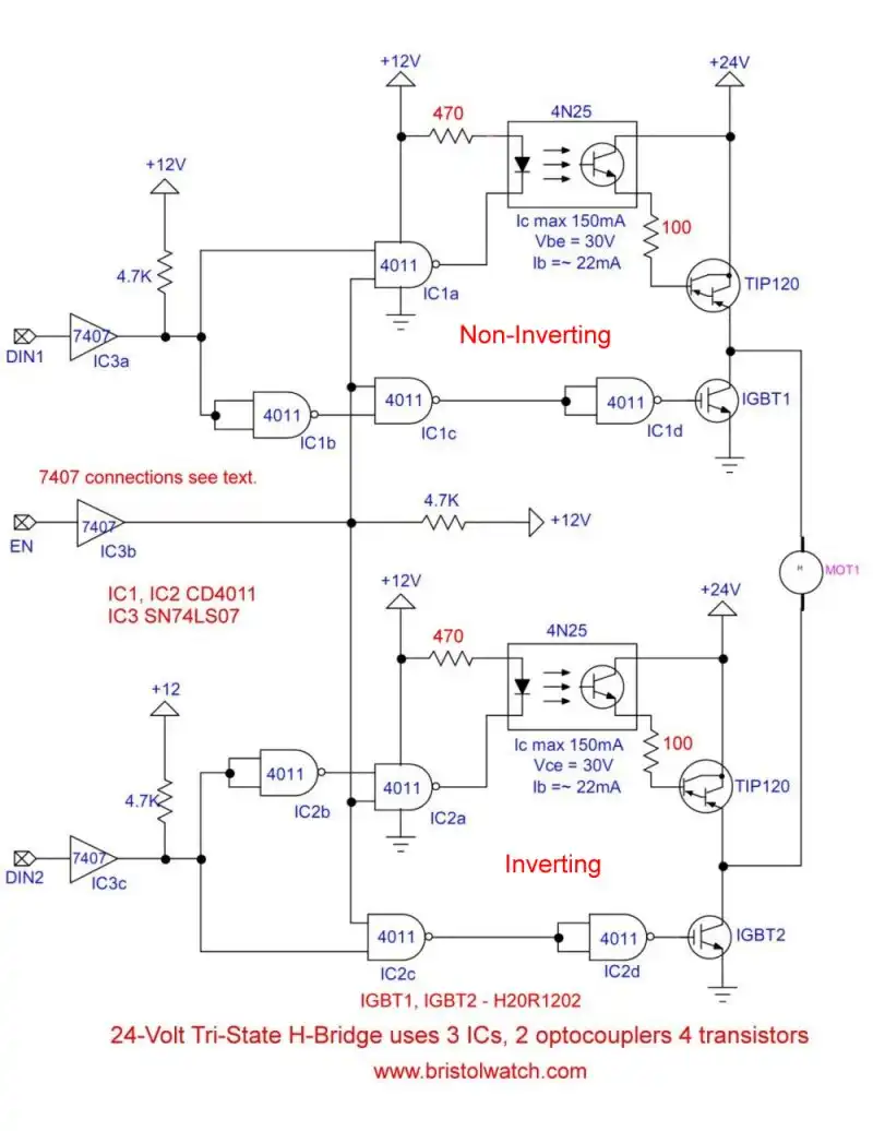
Fig. 1 Tri-State H-Bridge with Darlington-IGBT outputs.
Driving Darlington Transistors with Optocouplers
by Lewis Loflin
In this series I've illustrated a number of circuit combinations. In the schematic above I used a TIP120 Darlington power transistor for the high-side (Vcc) switch.
This was done because finding a high current, low resistance on p-channel MOSFET was difficult. The 2 p-channel MOSFETs I tried, the IRF9540 and IRF6930, overheated and dropped a lot of voltage. They are designed for high-voltage, low current, high frequency switching. Both had a high rds(sat) on resistance.
MOSFETs suffer from low source-gate voltage (Vgs) often limited to 20 volts. That means I can't use a 24, 36, or 48 volt motor without a complete circuit rework.
Note: the motor voltage must be separate from the 12 volt logic voltage in this example.
The TIP120 is rated 5-amps at 60-volts. While having a gain of 1000+ saturation is achieved at 20-30mA base current. That is easily supplied by a 4N25 type optocoupler. Rb is 100 Ohms.
Saturation voltage as measured across collector-emitter was 2.1V at 3.6 amps.
See Tutorial Using TIP120 and TIP125 Power Darlington Transistors.
The optocoupler not only provides voltage isolation for higher +Vcc but can produce more drive current that CMOS logic I used here.
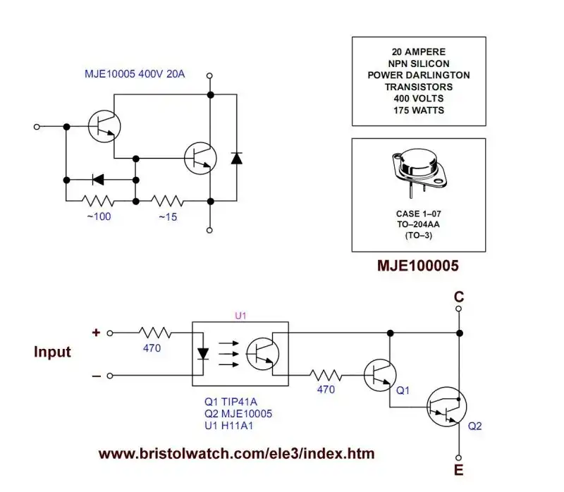
Fig. 2 Optocoupler driver for MJE10005 power Darlington transistor.
The MJE10005 provides much greater current capability and operates at a much higher voltage. But with a drive base current of 400mA to 2 amps no optocoupler I know of can supply that.
So I used a TIP41A transistor the optocoupler could drive then used that to drive the MJE10005.
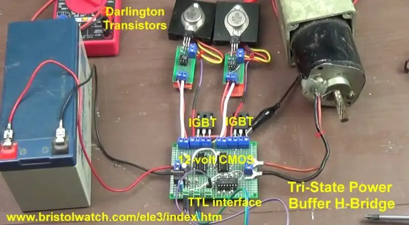
Fig. 3 Completed circuit with MJE10005 drivers used with IBGTs.
- Exploring Solid State Relays and Control Circuits
- Comparing Photo Triac, Photo SCR Opto-Couplers
- Light Activated SCR Based Optocouplers Circuit Examples
- Silicon Controlled Rectifier Review and Circuits
- Silicon Controlled Rectifiers Connected as Power Triacs
- Insulated Gate Bipolar Transistor IGBT Circuits
- Current Limiter Circuits for Opto-Coupler LEDs
- VOM1271 Photovoltaic MOSFET Driver Circuits
- Current Limiter Allows Safe Testing of Zener Diodes, LEDs
- 3 Amp LM741 Op-Amp Constant Current Source
- Bidirectional Solid State Relay Circuits
- Simple Solid State Relay for Low Power LED 120V Lamps
- Build High Power MOSFET Directional Switch Relay
- Optical Isolation of H-Bridge Motor Controls
- All NPN Transistor H-Bridge Motor Control
- Basic Transistor Driver Circuits for Micro-Controllers
- ULN2003A Darlington Transistor Array with Circuit Examples
- Tutorial Using TIP120 and TIP125 Power Darlington Transistors
- Driving 2N3055-MJ2955 Power Transistors with Darlington Transistors
- Understanding Bipolar Transistor Switches
- N-Channel Power MOSFET Switching Tutorial
- P-Channel Power MOSFET Switch Tutorial
- Build a Transistor H-Bridge Motor Control
- H-Bridge Motor Control with Power MOSFETS
- More Power MOSFET H-Bridge Circuit Examples
- Build a High Power Transistor H-Bridge Motor Control
- H-Bridge Motor Control with Power MOSFETS Updated
- Opto-Isolated Transistor Drivers for Micro-Controllers
- Comparator Theory Circuits Tutorial
- Constant Current Circuits with the LM334
- LM334 CCS Circuits with Thermistors, Photocells
- LM317 Constant Current Source Circuits
- TA8050P H-Bridge Motor Control
- All NPN Transistor H-Bridge Motor Control
- Basic Triacs and SCRs
- Comparator Hysteresis and Schmitt Triggers
- Comparator Theory Circuits Tutorial
- Photodiode Circuits Operation and Uses
- Optocoupler MOSFET DC Relays Using Photovoltaic drivers
- Connecting Crydom MOSFET Solid State Relays
- Photodiode Op-Amp Circuits Tutorial
- Optocoupler Input Circuits for PLC
- H11L1, 6N137A, FED8183, TLP2662 Digital Output Optocouplers
- Optical Isolation of H-Bridge Motor Controls
- All NPN Transistor H-Bridge Motor Control
© Copyright 2019 Lewis Loflin E-Mail