
Plate 1
N-Channel Power MOSFET Switching Tutorial
by Lewis Loflin
Webmaster Homepage and contact information.
Hobby Electronics Homepage.
Update Dec. 2019. Many micro-controllers today are using 3.3-volt Vcc. This is also true of Raspberry Pi. I found two MOSFETs that work at 3.3-volts.
The IRFZ44N is an N-channel device rated at 55V and RDS(on) resistance of 0.032 Ohms max. The other is a P-channel device rated at 55V and a RDS(on) of 0.02 Ohms max.
Here we will learn how power n-channel power MOSFETs operate. In this example I'm using enhancement mode devices. To use depletion mode MOSFETs simply reverse the circuits where an N-channel depletion mode MOSFET will use a variation of the P-channel enhancement mode circuit.
In plate 1 we have the symbols for depletion mode and enhancement mode MOSFETs - notice the dashed versus solid lines. In a depletion mode MOSFET gate voltage closes off the conductive channel from source (S) to drain (D). With an enhancement mode MOSFETs gate voltage opens the conductive channel from source to drain.
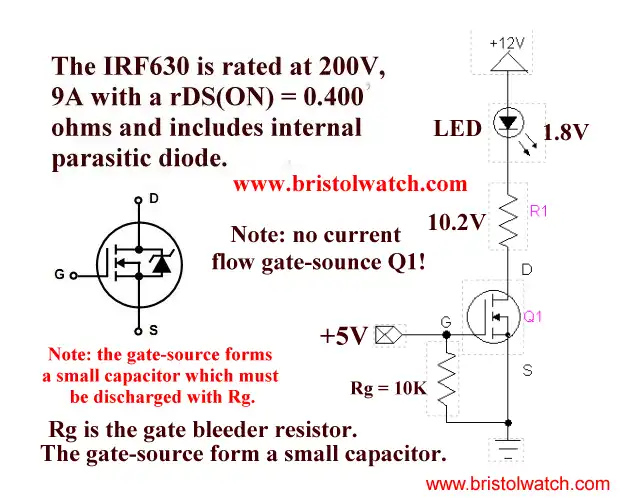
Plate 2
In the above examples we are switching a LED on/off using power MOSFETs. In the case of the N-channel such as the IRF630 when the gate (G) is greater than 5-volts the LED cuts on. The resistor on the gate of the N-channel MOSFET is used to bleed-off the electric charge from the gate and turn off the MOSFET. The resistor can be 5K-10K.
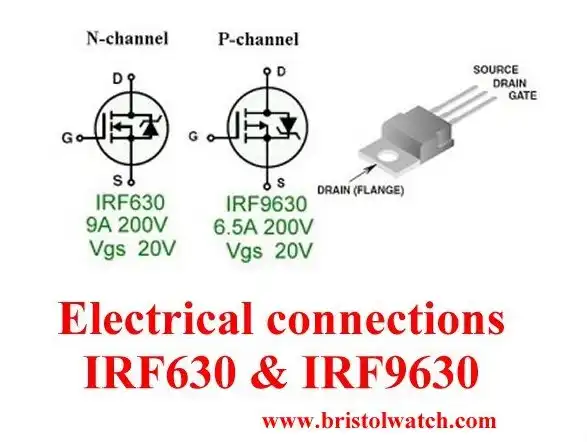
Plate 4
The voltage difference between the gate and source will turn on the MOSFET, but must not exceed a value in the spec sheet known as Vgs. To do so will damage the device. In the case of IRF630 and IRF9630 MOSFETs that value is 20-volts.
Note the internal parasitic suppression diodes are for use with magnetic loads. Not all power MOSFETs have those so check the specifications sheets. These particular transistors are optimized for switching and not for use in audio amplifiers.
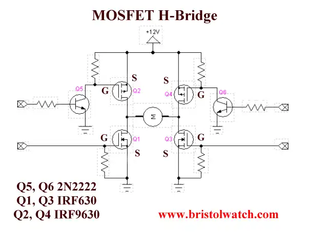
Plate 5
The largest use of these circuits is H-bridge motor controls. They are used in conjunction with N-channel MOSFET switches.
Note that Rg (or Rgs) is used to bleed the charges off the MOSFET gates or else they may not turn off.
- Quick navigation of this website:
- Basic Electronics Learning and Projects
- Basic Solid State Component Projects
- Arduino Microcontroller Projects
- Raspberry Pi Electronics, Programming
See the following spec sheets:
Also see Test Power MOSFET Transistors, Results, Observations
- ULN2003A Darlington Transistor Array with Circuit Examples
- Tutorial Using TIP120 and TIP125 Power Darlington Transistors
- Driving 2N3055-MJ2955 Darlington Transistors
- Understanding Bipolar Transistor Switches
- N-Channel Power MOSFET Switching Tutorial
- P-Channel Power MOSFET Switch Tutorial
- H-Bridge Motor Control with Power MOSFETs
- Arduino Controlled IR2110 Based H-Bridge HV Motor Control
- IGBT Based High Voltage H-Bridge DC Motor Control
- More Power MOSFET H-Bridge Circuit Examples
- Build a High Power Transistor H-Bridge Motor Control
- Related:
- N-Channel Power MOSFET Switching Tutorial
- P-Channel Power MOSFET Switch Tutorial
- Test Power MOSFET Transistors, Observations
- Issues on Connecting MOSFETs in Parallel
- Basic MOSFET Transistor Test Circuits
- High Voltage MOSFET Switching Circuits
- Why Your MOSFET Transistors Get Hot YouTube
- Issues on Connecting MOSFETs in Parallel YouTube
- Simple Circuits for Testing MOSFET Transistors YouTube
- Basic Triacs and SCRs
- Constant Current Circuits with the LM334
- LM334 CCS Circuits with Thermistors, Photocells
- LM317 Constant Current Source Circuits
- TA8050P H-Bridge Motor Control
- All NPN Transistor H-Bridge Motor Control
- Basic Triacs and SCRs
- Comparator Theory Circuits Tutorial
Web site Copyright Lewis Loflin, All rights reserved.
If using this material on another site, please provide a link back to my site.