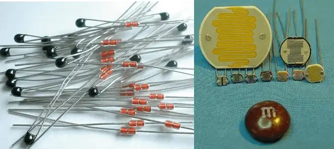
Fig. 1 Thermistors and CdS Photocells.
LM334 Constant Current Source with Resistive Sensors
Earlier we explored various constant current source circuits and settled for the LM334 as being the most stable for small current applications microamps though 10mA. We used the LM334 to control the emitter-base current in a PNP bipolar transistor to create a higher power constant current source to drive a bank of high-power white LEDs.
A constant current source (CCS) in electronics is a device/circuit that produces a constant value of current regardless of source voltage or load resistance.
Here we will take full advantage of the LM334 as a low-power precision constant current source to operate resistive sensors such as photocells and thermistors.
See LM334 Spec. Sheet. The LM334 is widely available for under $1 on EBAY.
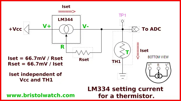
Fig. 2
Fig. 2 shows the basic circuit for a LM334 used as a series constant current sources (CCS) to bias a thermistor connected to an Arduino or PIC analog-to-digital converter. Note first we have a voltage input limit of 5-volts and both being 10-bit ADCs returns a value of 1023 based in voltage in. Volts per step is 5V / 1023 = 4.89mV per step.
As shown Iset is independent of input voltage Vcc and the resistance of Th1 The reason we should use a CCS is because Th1 produces a more linear output. By controlling Iset can set desired resistance vs. voltage point where we want in the 0-V range.
Vcc in all of these examples is 5-volts.
Here we will use thermistors from Sure Electronics - refer to sure_thermistors.pdf.
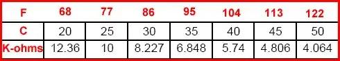
Fig. 3
Referring back to Hatching Chicken Eggs with Arduino I used a Sure thermistor with a resistor so Arduino could read the resulting voltage value to control temperature. The egg temperature had to be maintained at 37 degrees C (99 degrees F) for 21 days - and has to be fairly accurate. The chart in Fig. 3 was taken from the spec sheet.
What I want is a voltage reading at 37 degrees C of 2.5 volts on the ADC. Between 35 degrees C and 40 degrees C resistance varies from 6.848K ohms and 5.74K ohms - these are negative coefficient thermistors meaning the resistance decreases as temperature increases.
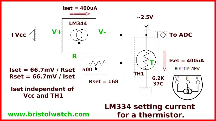
Fig. 4
Let's choose a value in between the two of 6.2K and assume 2.5-volts output to the Arduino ADC. 2.5V / 6200 = 400uA. This would be the value of Iset so we need to find the value of R in Fig. 4.
67.7mV / 400uA = 168 ohms. I used a 500 ohm potentiometer for calibration purposes - the 2.5-volt center gives plenty of room for adjustment.
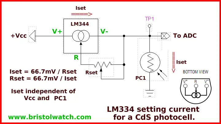
Fig. 5
In Fig. 5 we use the exact same circuit to control current through a CdS photocell. Everything works just the same - in this case we measure light intensity. In CdS photocells resistance decreases with light intensity.
- LM317 Adjustable Voltage, Current Boost Power Supply
- Constant Current Circuits LM334, LM317
- Build LM317 0-34 Volt Power Supply
- LM334 Constant Current Source with Resistive Sensors
- LM317 High Power Constant Current Source Circuit
- LM317 Constant Current Source Circuits
- Test SCRs and Triacs
- Basic MOSFET Transistor Test Circuits
- High Voltage MOSFET Switching Circuits
- 3 Amp LM741 Op-Amp Constant Current Source
- Current Limiter Testing of Zener Diodes
- Current Limiter for Opto-Coupler Inputs
- LM317 CCS for Light Emitting Diodes
- Experiments with TL431 Shunt Regulator
- TL431A Precision Current Regulator Circuits
- TL431A Based Current Limiter Constant Current Source Circuits
- TL431A Shunt Regulator Circuits
- Using TL431A Li-Ion Battery Charger Tutorials
- TL431A Lithium-Ion Cell Charging Circuits
- Charging Multi-Cell Lithium-Ion Battery Packs
- TL431 Over-Voltage, Under-Voltage Detector Circuits
- TL431A Constant Current Source Working Circuits Demo
Related YouTube video TL431A Lithium-Ion Cell Charging Circuits
Related YouTube video TL431 Battery Charger Circuit Calculations Revised
Related YouTube video TL431 10-Volt Charger Short Version
Related YouTube video Charging, Charge-Balancing 18V Li-Ion Battery with TL431
Related YouTube video 18.5V Li-Ion Battery Charger with TL431 (short)
- Arduino Measures Current from Constant Current Source
- Constant Current Source Theory Testing
- Arduino Controlled Power Constant Current Source
You Tube Videos
- Adjustable LM317 High Power Current Source
- Current Boost LM317 Adj. Power Supply
- LM317 Constant Current Source Circuits
Other Circuits
- Hall Effect Magnetic Switches and Sensors
- Comparator Theory Circuits Tutorial
- ULN2003A Darlington Transistor Array with Circuit Examples
- Transistor-Zener Diode Regulator Circuits
- AC Power Supply Rectification
- Coils for Highly Selective Crystal Radio
- Neon (NE-2) Circuits You Can Build
- Photodiode Circuits Operation and Uses
- Photodiode Op-Amp Circuits Tutorial
Web site Copyright Lewis Loflin, All rights reserved.
If using this material on another site, please provide a link back to my site.