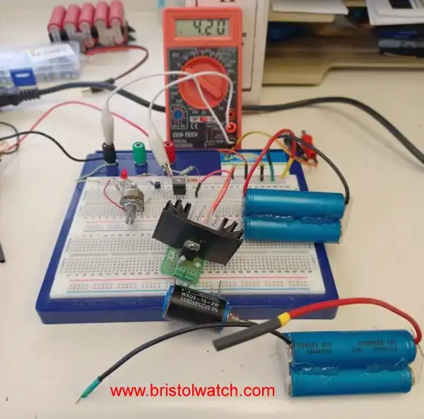
Fig. 1 Home built Lithium battery charger prototype.
TL431A Lithium-Ion Cell Charging Circuits
by Lewis Loflin
Follow @Lewis90068157
Here, the focus is safely charging lithium-ion cells and batteries. This tutorial will involve an upgraded TL431A Shunt Regulator Circuit combined with a constant current source based on an LM317.
Part 1 will explore single-cell charging circuits. Part 2 will concern multi-cell charging circuits.
In simple terms the TL431A acts a temperature compensated variable/adjustable Zener diode. It can also act as a voltage reference. In addition to good temperature compensation and stability, the TL431A has a voltage range of 2.5 volts to 36 volts and a current range from 1mA to 100mA.
For basic information on the TL431 see Experiments with TL431A Shunt Regulator
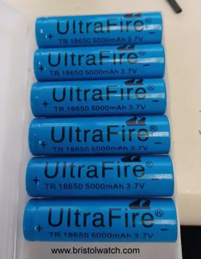
Fig. 2 UltraFire 18650 Lithium Cells rated 5000mAh at 3.7V.
Also, this tutorial will address serial-parallel battery connections and safety considerations:
Over-charging or shorting out lithium-ion batteries can result in fire or even explosions! What I present here is, for information purposes, use at one's own risk. Fire is a serious issue for lithium cells due to their high energy density!
The current density is so high I have observed wiring catching fire and the cell casing melting! These charger circuits will have safety features lacking in many designs on the internet.
Definition: a "cell" is a single chemical or electrical unit. A battery is a group of cells.
In Fig. 1, the three-cell battery packs, note the red leads. These three cells (salvaged from a laptop battery) are connected in parallel (plus to plus); at 3.7V, 2300mAh each add to 3.7V at 6900mAh. Notice the black heat shrink over the ends of the red wires. This precaution assures no shorted connections during storage.
As for milli-ampere-hour (mAh) the definition is,
It is a measure of battery capacity. Electronics use, or draw, energy that's measured in amperes(A). So a 1500mAh battery can power an electronic device with a draw of 1mA for 1500 hours, or a device that draws 1.5A for one hour.
If one connected three of the Ultra Fire 5000mAh in parallel, this could supply 15,000mAh or 15 amperes for one hour. Don't try drawing that much current! I suggest no more than 20% of continuous maximum current or, in this example, 3 amperes.
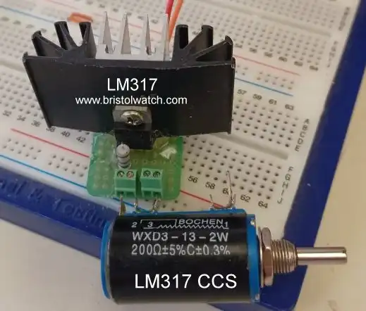
Fig. 3
Fig. 3 is an LM317 variable constant current source prototype. I replaced the 200 Ohm potentiometer with a ~6.25 Ohm resistor combination for 200mA in the schematics. The formula is 1.25 / R or 1.25/6.25 = 200mA. Note the screw terminals to connect the potentiometer or a fixed resistor.
For several tutorials on constant current sources using the LM317 see the following:
See LM317 Constant Current Source Circuits.
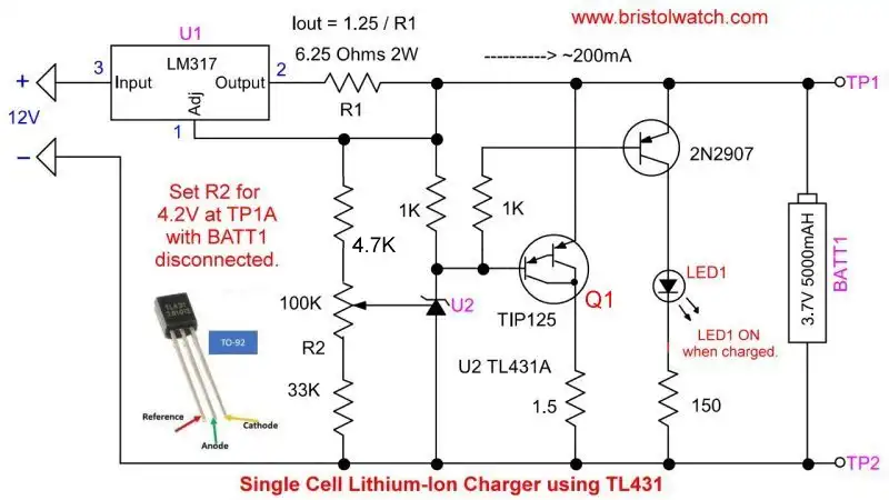
Fig. 4
Fig. 4 is a variation of my TL431A Shunt Regulator Circuit. I replaced the Rin resistor with an LM317 constant current source circuit.
Next I replaced the Q1 PNP transistor with TIP125 PNP Darlington transistor. This substitution gives better performance and current handling capability. I added a 1.5 Ohm, 1-watt resistor to the Q1 collector circuit. Besides dissipating some heat when Q1 switches on, it will act as a fuse in case Q1 becomes shorted, preventing a possible fire from the cell under charge..
Finally, I added a 2N2906 transistor and a "fully charged" indicator LED. This circuit is a trickle charging system.
U1 is an LM317 CCS circuit. R1 controls the charge current. 6.25 Ohms produces 200mA, a 10 Ohm resistor produces 125mA, 2.7 Ohm produces ~462mA. Heat sink Q1 and the LM317.
The TL431A (U2) turn on point is controlled by potentiometer R2 and a 33K resistor. When U2 turns on, current flow (cathode to anode) is shunted through the Q1 base-emitter, turning on Q1, shunting excess current to ground, maintaining a fixed charge voltage that R2, a 100K pot, set. Current is also shunted through the 2N2907 base-emitter, turning on the transistor and LED.
Note there are 3.2-volt LiFePO4 Lithium Phosphate Batteries that should be charged at 3.6V. The 3.7-volt cells charge at 4.2-volts. This circuit will not work below 2.9V.
Setup:
1. Disconnect any cell or battery pack, and connect power.
2. Connect a voltmeter from TP1 to TP2, and adjust R2 for the desired charge voltage limit.
3. Disregard the LED.
Disconnect power, reconnect the cell to be charged and apply power. The input voltage should be 5 volts above the charge voltage for reliable operation of the LM317. This single-cell circuit originally used a 9-volt, 300mA power supply.
When an uncharged cell is connected, TP1 voltage will be below 4.2V, LED is off. When the cell is fully charged at 4.2V, any further charge current is shunted through Q1, LED turns on.
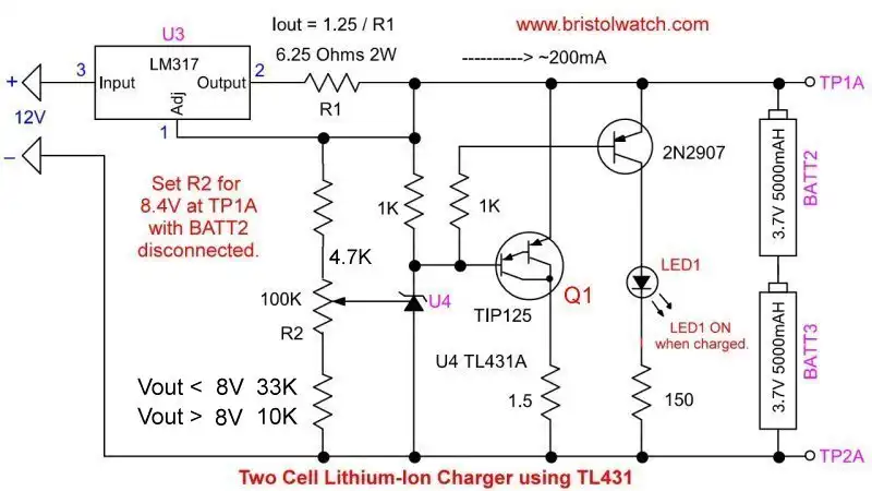
Fig. 5
Fig. 5 is identical to Fig. 4 other than setting a different charge voltage. With two cells in series and both being charged at 4.2V, the charge voltage must be 8.4V. Use a 12V or greater supply for this.
To determine the input voltage, multiply the number of cells by charge voltage and add 5 volts.
Setup is the same, disconnect BATT2 or BATT3. Connect the voltmeter from TP1A to TP2A, connect power, and adjust R2 for 8.4V. Disregard the LED. Remove power and reconnect the cell. Apply power.

Fig. 6
This circuit will charge any number of cells or battery packs from 3-volts to ~20 volts with modifications.
Fig. 6 illustrates a six-cell, 7.2-volt nickel-cadmium battery pack rated at 400mAh. To quote,
The nickel–cadmium battery system has a nominal voltage of 1.2 V/cell. The typical end voltage for discharge is 0.9–1.0 V/cell, and the typical end voltage for charging varies between 1.45 and 1.6 V/cell, depending on battery, controller, and system type.
With six cells (1.2V X 6 = 7.2V) one must set a charge voltage of 1.45 X 6 = 8.7V. The procedure is the same as above. With a 400mAh battery pack, lower the charge current from 200mA. Change R1 in the LM317 circuit to 10 Ohms for 125mA or 22 Ohms for ~50mA.
Lower charging rates extend battery life. A high charging current can overheat the battery.
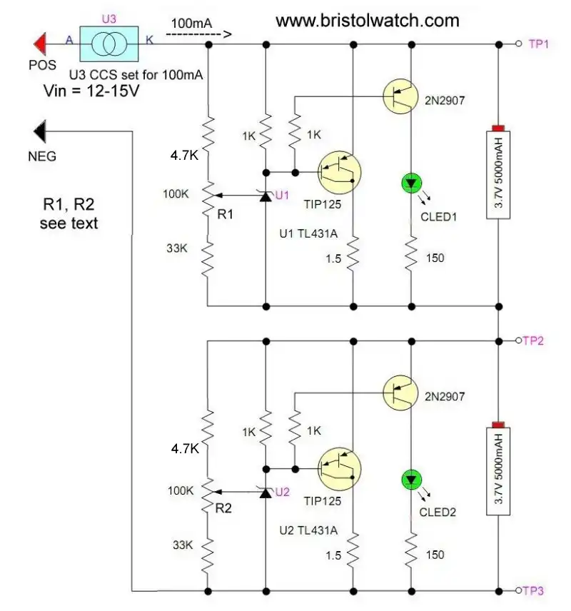
Fig. 7
For a discussion of multi-cell lithium battery chargers see Charging Multi-Cell Lithium-Ion Battery Packs.
- Experiments with TL431 Shunt Regulator
- TL431A Precision Current Regulator Circuits
- TL431A Based Current Limiter Constant Current Source Circuits
- TL431A Shunt Regulator Circuits
- Using TL431A Li-Ion Battery Charger Tutorials
- TL431A Lithium-Ion Cell Charging Circuits
- Charging Multi-Cell Lithium-Ion Battery Packs
- TL431 Over-Voltage, Under-Voltage Detector Circuits
- TL431A Constant Current Source Working Circuits Demo
- Example of Applied Reason with Electronics
Related YouTube video TL431A Lithium-Ion Cell Charging Circuits
Related YouTube video TL431 Battery Charger Circuit Calculations Revised
Related YouTube video TL431 10-Volt Charger Short Version
Related YouTube video Charging, Charge-Balancing 18V Li-Ion Battery with TL431
Related YouTube video 18.5V Li-Ion Battery Charger with TL431 (short)
- Arduino Measures Current from Constant Current Source
- Constant Current Source Theory Testing
- Arduino Controlled Power Constant Current Source
- LM317 Adjustable Current Boost Power Supply
- Constant Current Circuits LM334, LM317
- Build LM317 0-34 Volt Power Supply
- LM334 Constant Current Source with Resistive Sensors
- LM317 High Power Constant Current Source Circuit
- LM317 Constant Current Source Circuits
- Test SCRs and Triacs
- Basic MOSFET Transistor Test Circuits
- High Voltage MOSFET Switching Circuits
- 3 Amp LM741 Op-Amp Constant Current Source
- Current Limiter Testing of Zener Diodes
- Current Limiter for Opto-Coupler Inputs
- LM317 CCS for Light Emitting Diodes
Other Circuits
- Hall Effect Magnetic Switches and Sensors
- Comparator Theory Circuits Tutorial
- ULN2003A Darlington Transistor Array with Circuit Examples
- Transistor-Zener Diode Regulator Circuits
- AC Power Supply Rectification
- Coils for Highly Selective Crystal Radio
- Neon (NE-2) Circuits You Can Build
- Photodiode Circuits Operation and Uses
- Photodiode Op-Amp Circuits Tutorial
Web site Copyright Lewis Loflin, All rights reserved.
If using this material on another site, please provide a link back to my site.