Fig. 1a
Charging Multi-Cell Lithium-Ion Battery Packs
by Lewis Loflin
The topics covered here are testing and charging salvaged Li-Ion cells and batteries.
Related YouTube video TL431A Lithium-Ion Cell Charging Circuits
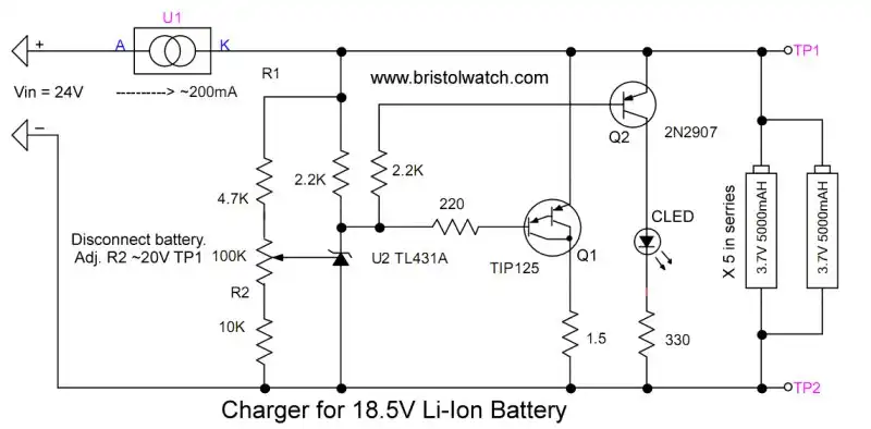
Fig. 1 is identical to charging a single Li-Ion cell other than setting a different charge voltage. With two cells in series and both being charged at 4.2V, the charge voltage must be 8.4V. Use a 12V or greater supply for this.
To determine the input voltage, multiply the number of cells by charge voltage and add 5 volts.
Setup: disconnect BATT2 or BATT3. Connect the voltmeter from TP1A to TP2A, connect power, and adjust R2 for 8.4V. Disregard the LED. Remove power and reconnect the cell. Apply power.
When the two cells are charged the LED will turn on.
Simple enough, but what about large numbers of cells in series? What about voltage variations between individual cells? Or series-parallel combinations? Those issues will be explored here.
See part 1 TL431A Lithium-Ion Cell Charging Circuits for the TL431A circuit operation.
Once again a safety warming:
Over-charging or shorting out lithium-ion batteries can result in fire or even explosions! What I present here is, for information purposes, use at one's own risk. Fire is a serious issue for lithium cells due to their high energy density!

Fig. 2a
Three lithium-ion cells connected in parallel. Current capacity adds. The charging circuits will sense a single cell.
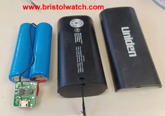
Fig. 3a
Uniden power pack has 2 lithium-ion cells. This consists 2 parallel connected Li-Ion cells and a small charging circuit.
The unit can supply 1A max with a capacity of 3000mAh.
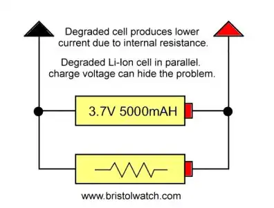
Fig. 4a
(Above) Two lithium-ion cells connected in parallel. Current capacity may add, but degraded or dead (or open) cells produce less overall power. The charging circuit based on voltage alone can miss this problem.
These cells must be tested under load based on a known charge voltage. Salvage Li-Ion cells, for example, from laptop batteries, may have no part numbers or identifying information.
In the case of Fig. 1a with two cells in series, after charged disconnect from the charging circuit. Place a 10-Ohm 10-watt resistor across the series pair. Measure each cell with a voltmeter. The voltage drop difference between individual cells should be a few milli volts. A difference of more than 5% could cause future problems.
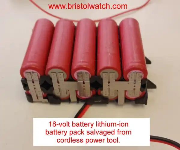
Fig. 5a
Above is an 18 volt lithium-ion battery removed from cordless tool power pack. This was discarded from a work site. Internal to the power pack was a "charge balancing" circuit board that failed. All the Li-Ion cells still had some charge.
If any the cells are below 2.5-3V they could be bad. I charged one cell (not part of this battery pack) from nearly dead and it worked fine.
There were no part numbers on the cells, so I don't know the current capacity.
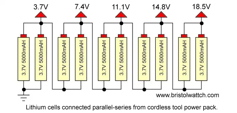
Fig. 6a
The schematic of the battery is shown in Fig. 6a. This consists of 10 Li-Ion cells connected as five parallel sets wired in series. There were six solder connections to the failed charge balancing circuit board, as shown.
Each cell pair, when measured with a voltmeter, read over 3V. This number is good news. But should one try to charge the battery as a single 18.5 battery?
Because I had access to the six connections for all cell pairs, I charged each pair to 4.2V at 200mA separately. See TL431A Li-Ion Cell Charging Circuits
As for milli-ampere-hour (mAh) the definition is,
It is a measure of battery capacity. Electronics use, or draw, energy that's measured in amperes(A). So a 1500mAh battery can power an electronic device with a draw of 1mA for 1500 hours, or a device that draws 1.5A for one hour.
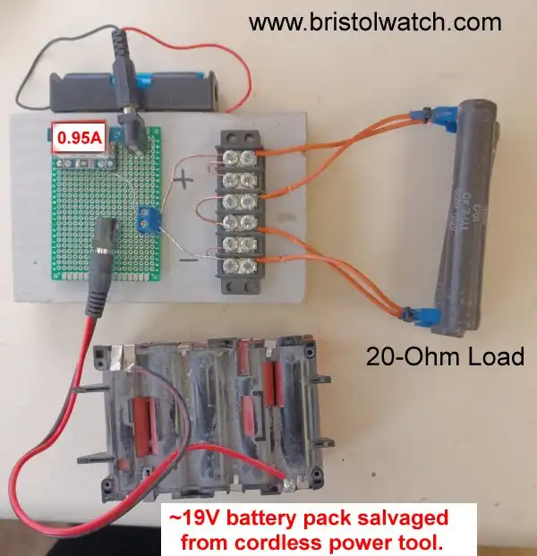
Fig. 7a
In Fig. 7a, the battery was tested using a 20-Ohm load. The amp meter indicated 0.94A current. I let this operate for several minutes, and the resistors got hot. All voltage drops across the five pairs of cells indicated a difference of no more than 0.04V. This reading indicated that the battery is good.
The battery is charged as a single 18.5V battery through a constant current source. The charge circuit is set for ~19-21V while connecting the CCS to a 24V supply.
The circuit in Fig. 1a can be used; I tested it at 19.5V, but had to change the 33K resistor to 10K. In addition add a 220 Ohm resistor from Q1 base to the TL431. This limits Ika to under 100mA
Calculating Charge Voltage Resistors
The input voltage Vin must be 4V-5V or greater above the charge voltage as a general rule.
R1 is the 100K + 4.7K, R2 sets the upper and lower range. 4.7K was added to limit the TL431 Ref current to under 10mA at 24V: 24 / 4.7K = 5.1mA. VRef = 2.5V.
Note: due to VRef = 2.5V and circuit voltage being low this circuit doesn't work under ~3.2V.
The formula using 33K for R2 is Vout MAX = (1 + (104.7K / 33K)) * 2.5V = (1 + ~3.17) * 2.5 = 4.17 * 2.5 = ~10.43V.
For Vout MIN with 33K = (1 + (4.7K / 133K)) * 2.5V = (1) * 2.5 = ~2.5V.
So our voltage range is 2.5V to ~10V. If one desires a charging voltage over 10V then R2 must be changed to a lower value.
The formula using 10K Vout MAX = (1 + (104.7K / 10K)) * 2.5V = (1 + 10.47) * 2.5 = ~28.7V.
For Vout MIN with 10K = (1 + (4.7K /110K)) * 2.5 = 1 * 2.5V = ~2.5V.
Note: due to VRef = 2.5V and circuit voltage being low this circuit doesn't work under ~3.2V.
So the range with 10K is ~2.5V to ~28.7V. I won't use a power supply above 25.2V so this value is fine.
Note: the power supply says on the label 24V but measures 25.2V.
In this case I'll use a 10K for R2.
Disconnect a battery connection. Apply 24V, adjust R2 for 19-20V. Disconnect power, connect the battery, and apply power.
This is fine as long as all cell pairs are identical and in the same electrical condition. This series configuration is how car batteries (6, 2.2V cells in series) and cordless phone batteries (6, 1.2V cells in series) are charged.
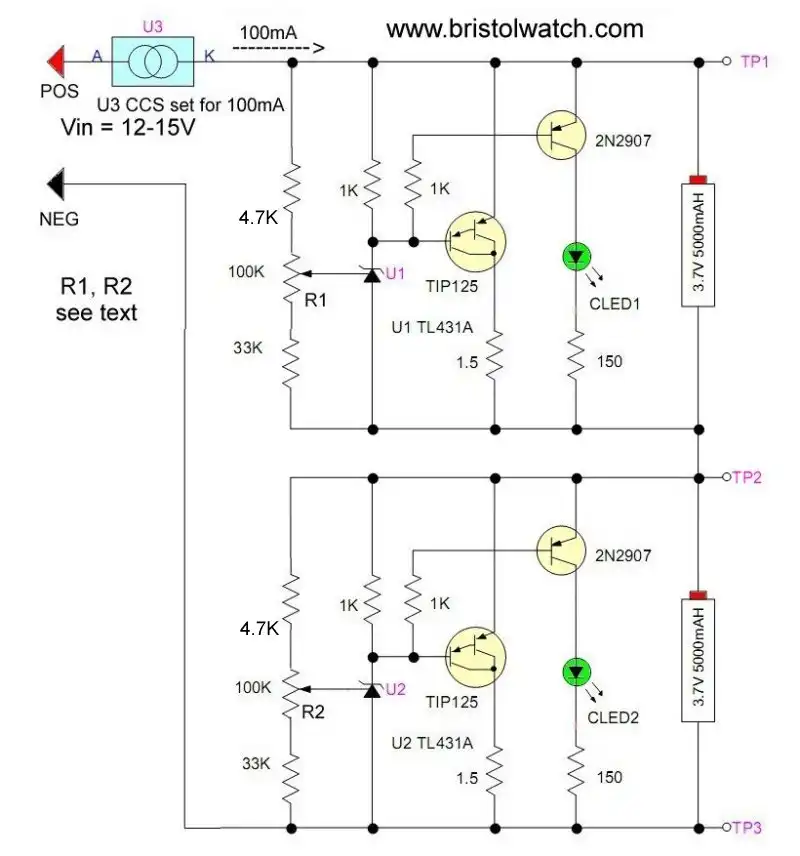
Fig. 8a
Fig. 8a is a two-cell charge balancing circuit. Each cell has its individual charge circuit set to 4.2V.
In the case of the battery in Fig. 6a would require one charge controller per cell pair, or five units in this case.
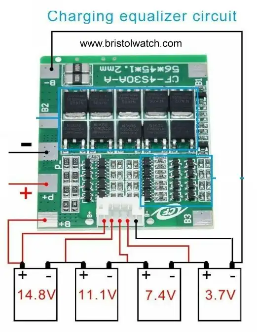
Fig. 9a
Fig. 9a illustrates a 4-cell charge controller from Ebay.
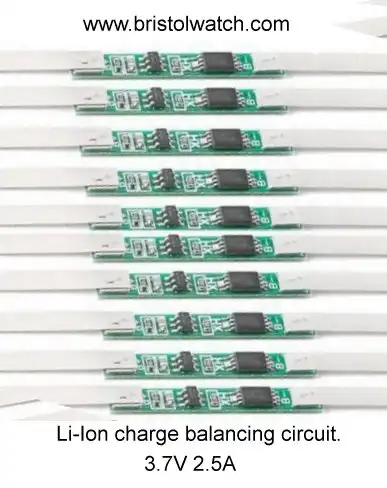
Fig. 10a
Fig. 10a illustrates a Li-Ion cell charge controller in strip form. Rated at 2.5A, five would be required for the battery pack in 6a.
I tested these, and they work as advertised. They are marked "+" and "-" and can be soldered directly to the cell.
- Using TL431A Li-Ion Battery Charger Tutorials
- TL431A Lithium-Ion Cell Charging Circuits
- Charging Multi-Cell Lithium-Ion Battery Packs
- TL431 Over-Voltage, Under-Voltage Detector Circuits
- TL431A Constant Current Source Working Circuits Demo
- Power TL431 Constant Current Source Circuits
- TL431, LM317 Battery Charger Circuits Schematics
Related YouTube videos.
- TL431 12V Battery Charger Complete
- TL431A Lithium-Ion Cell Charging Circuits
- TL431 Battery Charger Circuit Calculations Revised
- TL431 10-Volt Charger Short Version
- Charging, Charge-Balancing 18V Li-Ion Battery with TL431
- 18.5V Li-Ion Battery Charger with TL431 short version
- TL431 Under-Voltage, Over-Voltage Detection
- TL431 Constant Current Source Circuits
- TL431 Power Constant Current Source Demo 1
- Arduino Measures Current from Constant Current Source
- Constant Current Source Theory Testing
- Arduino Controlled Power Constant Current Source
- LM317 Adjustable Current Boost Power Supply
- Constant Current Circuits LM334, LM317
- Build LM317 0-34 Volt Power Supply
- LM334 Constant Current Source with Resistive Sensors
- LM317 High Power Constant Current Source Circuit
- LM317 Constant Current Source Circuits
- Test SCRs and Triacs
- Basic MOSFET Transistor Test Circuits
- High Voltage MOSFET Switching Circuits
- 3 Amp LM741 Op-Amp Constant Current Source
- Current Limiter Testing of Zener Diodes
- Current Limiter for Opto-Coupler Inputs
- LM317 CCS for Light Emitting Diodes
Other Circuits
- Hall Effect Magnetic Switches and Sensors
- Comparator Theory Circuits Tutorial
- ULN2003A Darlington Transistor Array with Circuit Examples
- Transistor-Zener Diode Regulator Circuits
- AC Power Supply Rectification
- Coils for Highly Selective Crystal Radio
- Neon (NE-2) Circuits You Can Build
- Photodiode Circuits Operation and Uses
- Photodiode Op-Amp Circuits Tutorial
Web site Copyright Lewis Loflin, All rights reserved.
If using this material on another site, please provide a link back to my site.