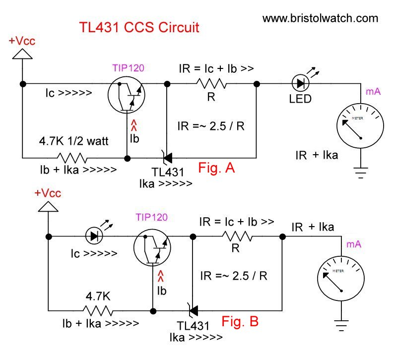
Fig. 1 TL431 current source and current sink schematics.
TL431A Constant Current Source Working Circuits Demo
by Lewis Loflin
Follow @Lewis90068157
For the background on TL431 CCS circuits see TL431A Based Current Limiter Constant Current Source Circuits.
This page concerns the use of the constant current source configuration Fig. 1 A. The NPN transistor used in the specification sheet example, with little useful information, has been replaced by a TIP120 NPN Darlington transistor. This produces better output characteristics than an NPN.
The current formula is 2.5 / R. Figures 2 through 5 below illustrate the test set up and the calculated and measured results for an R value of 15, 47, and 150 Ohms.
The test load is a white power LED that operates at a measured ~2.8V. Notice the smaller value of R the brighter the LED due to higher current. Notice the heat sink on the LED.
The TL431 cathode and Ref pins control the Base-Emitter current of the TIP120. The resistor R is connected between Ref and the anode. This controls the TIP120 base current from the TL431 Cathode-Ref pins. The 4.7K resistor supplies the cathode current for the TL431. This can be dropped to 3.3K or 2.7K.
The measured voltage across R ranges from from 2.4V to 2.5V. The power value for R in watts is the current X resistance. For example, a 10-Ohm value for R produced 250mA: 250mA X 2.5V = 625mW. Use a 1 or 2 watt resistor.
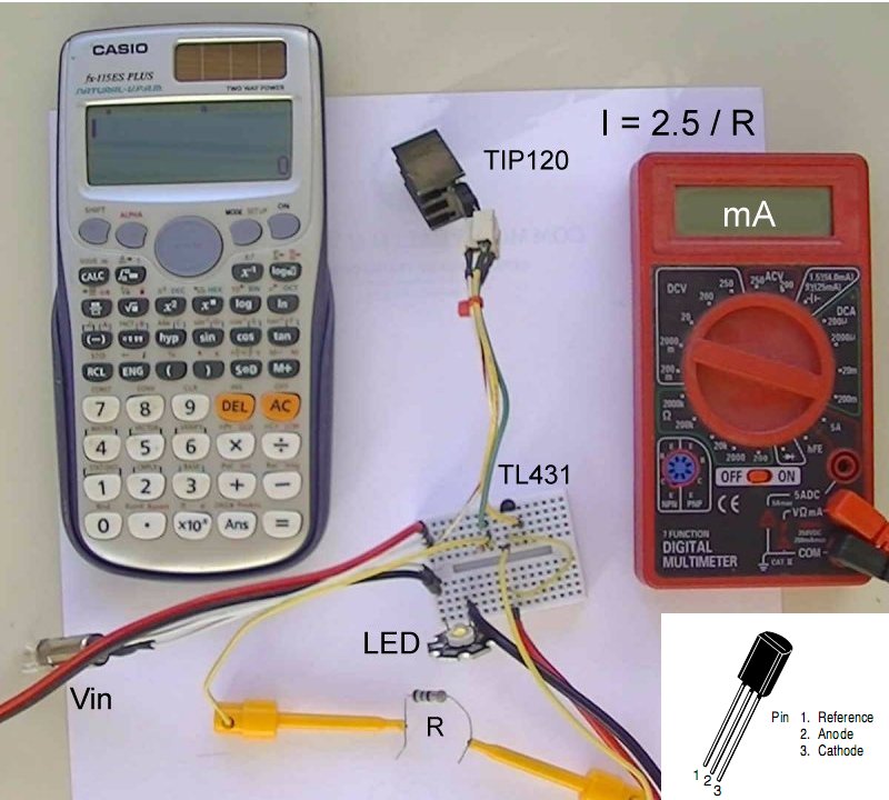
Fig. 2 TL431 power constant current source test setup.
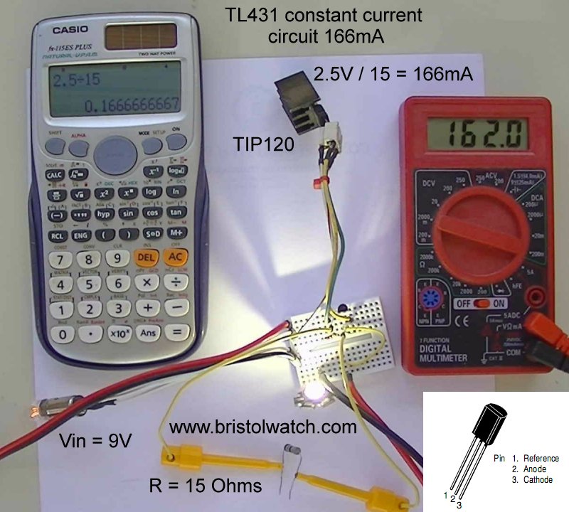
Fig. 3 TL431 power constant current source test with 15-Ohm resistor. Current = 166mA.
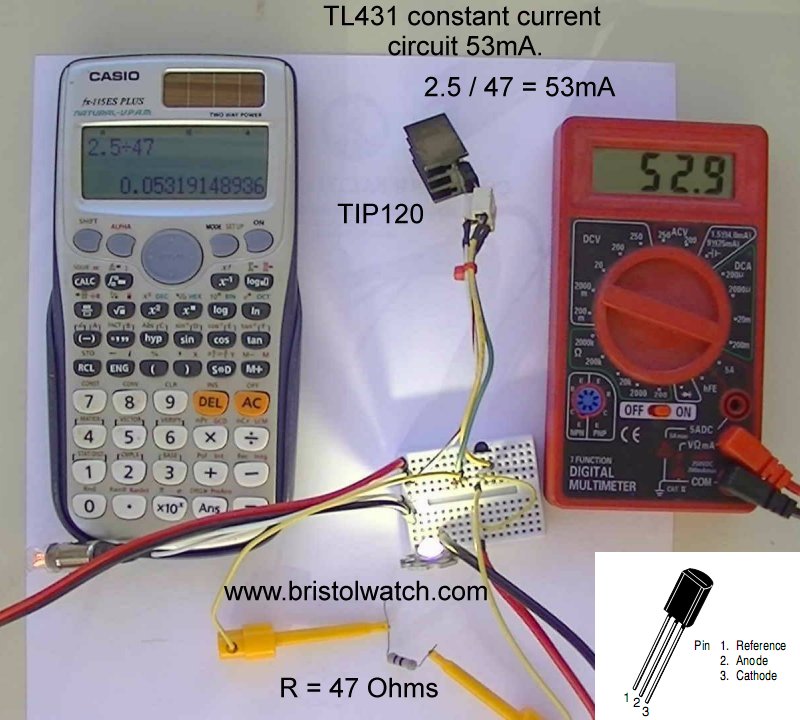
Fig. 4 TL431 power constant current source test with 47-Ohm resistor. Current = 53mA.

Fig. 5 TL431 power constant current source test with 15-Ohm resistor. Current ~17mA.
The current outputs closely follow the calculated values. A 10-Ohm resistor for R produced 250mA. A 5-Ohm for R started to reveal some problems. The TL431A is a low power device while the TIP120 Darlington is a much higher power device. This was stressing and starting to heat the TL431 above 400mA.
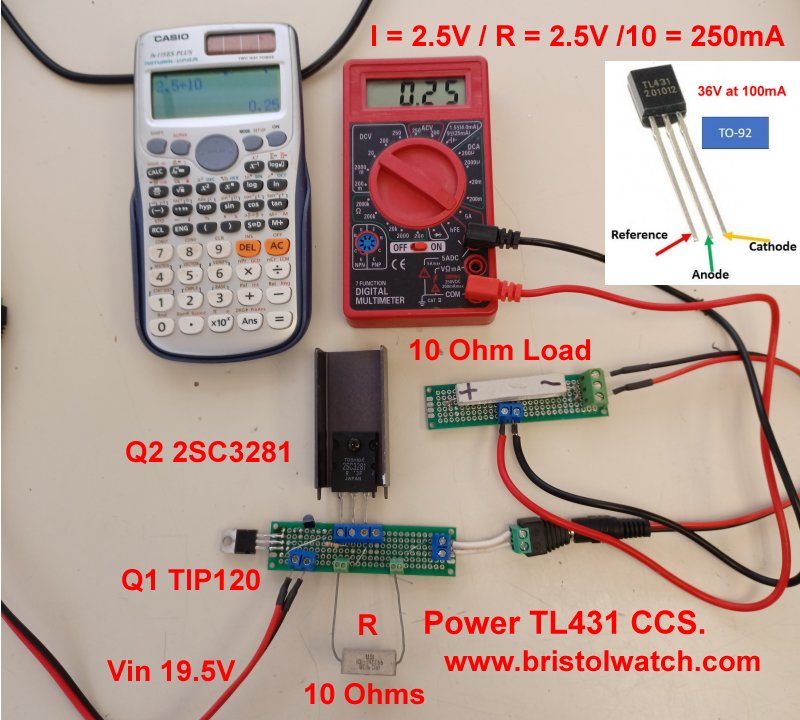
Fig. 6 TL431 power constant current source test setup 2.
Current Boost
A new test setup is shown above. The TL431A CCS circuit was built on a PC board. Screw block are used for power input, power output, for current set resistor R, and for an additional NPN transistor Q2. The original circuit above used the TL431A to drive a TIP120 Darlington power transistor. Now that TIP120 drives Q2 a higher power NPN pass transistor.
The input voltage is 19.5V and the test load of a 10-Ohm 10-watt resistor. A cheap Harbor Fright voltmeter measures the current.
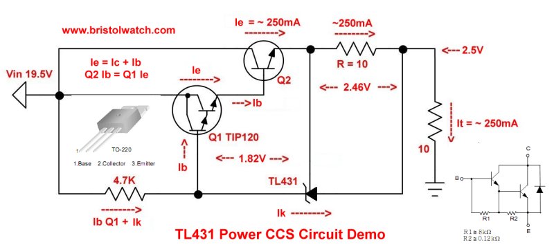
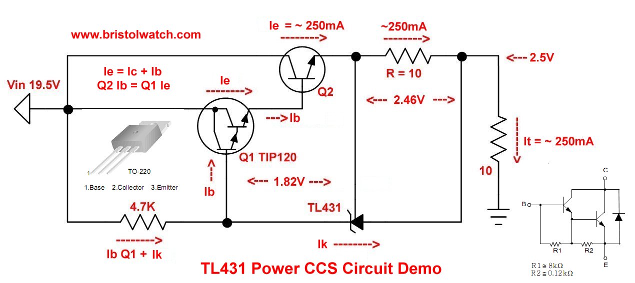
Fig. 7 TL431 constant current source power demo schematic.
For a larger image of above click tl431_power_ccs.jpg
The revised schematic is shown in Fig. 7. A 5-Ohm value for R produced 500mA as expected. A 2-Ohm value for R produced 1.136A. A 1-Ohm value for R produced only 2A max. I would limit R to no lower than 1.5-Ohms.
At 19.5V, ~2.5V is dropped across R, 2.5V across the 10-Ohm load. Then 14.5V is dropped across Q2. To cut down on wasted power reduce Vin from 19.5V to 10V.
While Q2 is a 2SC3281, it can be any NPN power transistor such 2N3055.
- Experiments with TL431 Shunt Regulator
- TL431A Precision Current Regulator Circuits
- TL431A Based Current Limiter Constant Current Source Circuits
- TL431A Shunt Regulator Circuits
- Using TL431A Li-Ion Battery Charger Tutorials
- TL431A Lithium-Ion Cell Charging Circuits
- Charging Multi-Cell Lithium-Ion Battery Packs
- TL431 Over-Voltage, Under-Voltage Detector Circuits
- TL431A Constant Current Source Working Circuits Demo
Related YouTube video TL431A Lithium-Ion Cell Charging Circuits
Related YouTube video TL431 Battery Charger Circuit Calculations Revised
Related YouTube video TL431 10-Volt Charger Short Version
Related YouTube video Charging, Charge-Balancing 18V Li-Ion Battery with TL431
Related YouTube video 18.5V Li-Ion Battery Charger with TL431 (short)
- Arduino Measures Current from Constant Current Source
- Constant Current Source Theory Testing
- Arduino Controlled Power Constant Current Source
- LM317 Adjustable Current Boost Power Supply
- Constant Current Circuits LM334, LM317
- Build LM317 0-34 Volt Power Supply
- LM334 Constant Current Source with Resistive Sensors
- LM317 High Power Constant Current Source Circuit
- LM317 Constant Current Source Circuits
- Test SCRs and Triacs
- Basic MOSFET Transistor Test Circuits
- High Voltage MOSFET Switching Circuits
- 3 Amp LM741 Op-Amp Constant Current Source
- Current Limiter Testing of Zener Diodes
- Current Limiter for Opto-Coupler Inputs
- LM317 CCS for Light Emitting Diodes
Other Circuits
- Hall Effect Magnetic Switches and Sensors
- Comparator Theory Circuits Tutorial
- ULN2003A Darlington Transistor Array with Circuit Examples
- Transistor-Zener Diode Regulator Circuits
- AC Power Supply Rectification
- Coils for Highly Selective Crystal Radio
- Neon (NE-2) Circuits You Can Build
- Photodiode Circuits Operation and Uses
- Photodiode Op-Amp Circuits Tutorial
Web site Copyright Lewis Loflin, All rights reserved.
If using this material on another site, please provide a link back to my site.