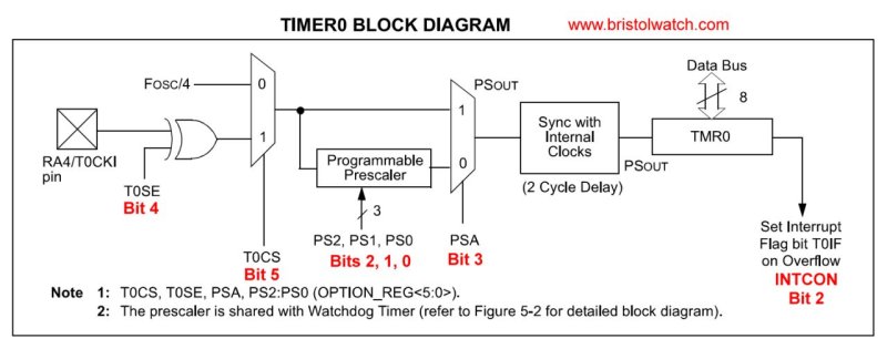
Fig. 1 TMR0 block diagram.
Programming PIC16F84A-PIC16f628A Timers by Example
by Lewis Loflin
Follow @Lewis90068157
A PIC16F84A has one 8-bit hardware timer TMR0 while a PIC16F628A has the same thing plus two additional timers TMR1 (16-bit) and TMR2 which is 8-bit. Here I'm concerned only with TMR0 and its prescaler that divides the clock frequency from 1:2 to 1:256 configured by three bits in the OPTION register shown in Fig. 1. Bit 0 - 5 are used to configure the TMR0 operation.
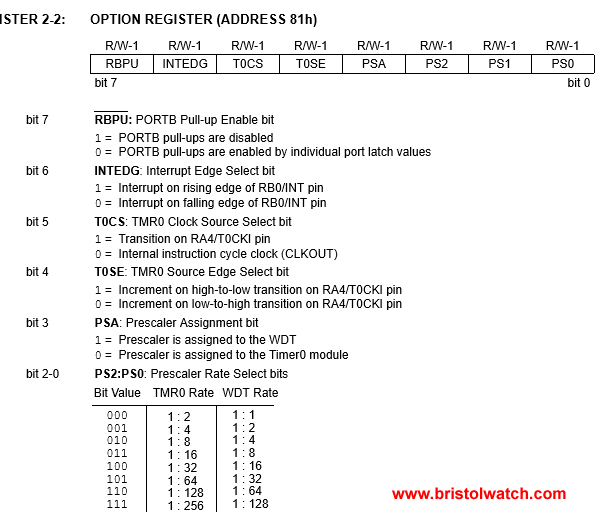
Fig. 2 Option Register.
In Fig. 1 is the internal block diagram for TMR0. We can select an internal clock source which is crystal frequency divided by 4 or an external clock from RA4. Assuming a 4mHz crystal we can use the 1uS count directly or divide by 8 different values up to 256. After 256 counts TMR0 sets its overflow bit (INTCON bit 2) which is 1 on overflow and 0 otherwise.
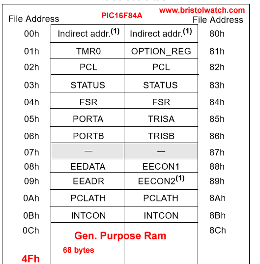
This flag must be cleared back to zero (BCF, INTCON, 2) before the timer can be used again. The TMR0 register is in BANK0, 0x01. The precount value must be written to the TMR0 register before clearing the overflow flag and done each time the timer is used.
With 0x00 in the TMR0 register, the prescaler at divide by 256, and a 4mHz clock (1uS per tick) the TMR0 flag will be set after 256 X 256 uSec = 65,536 uSec or 65.536 milli seconds. Let's look at some actual working code.
In SETUP I've set the OPTION_REG in BANK1 for TMR0 internal clock, low-to-high transition, prescaler divide by 256. LOOP uses a XOR command to toggle the state ON-OFF of a LED on PB0 then call TMR0_DEL. In subroutine TMR0_DEL we programmed TMR0 to overflow at 50mSec by storing 59 in the TMR0 register. COUNT1 is loaded with a count X for ever how may 50mSec. we need. 5 * 50mSec. = 250mSec.
Then we clear the TMR0 overflow flag (BCF, INTCON, 2) then wait until it's set again. (BTFSZ, INTCON, 2) It then decrements COUNT1 that when it reaches zero will exit the subroutine.
;========================================
;	CLOCK: External 4MHz (instruction execution time: 1usec)
;	This is a basic start template for PIC16F84A
;	Includes delay routines
;	Program name: TMR0 Delay Non-Interrupt
;	Date: 6-16-2024
;	Author: Lewis Loflin
;	MPLAB v8.92	compiles to 29 bytes.
;========================================

	list      p=16F84A ; list directive to define processor
	#include <p16F84A.inc> ; processor specific variable definitions
	errorlevel  -302 ; Ignore error message when storing to Bank 1.

  	__CONFIG  _CP_OFF & _PWRTE_ON & _WDT_OFF & _XT_OSC

;=========================================

;*****[ Data Storage Reg's ]*****
            CBLOCK  0x0C ; Assign each reg. from Bank 0 RAM area.
            CNT1
            CNT2
			CNT3
			CNT4
            TEMP1
            TEMP2
            ENDC  ; Conclude Bank 0 RAM assignments.

;**********************************************************************
	ORG     0x000             ; processor reset vector
	goto    setup              ; go to beginning of program

	ORG     0x004             ; interrupt vector location
	retfie                    ; return from interrupt

;**********************************************************************

setup

     ; BSF	STATUS,RP0 ;Jump to bank 1 use BANKSEL
	BANKSEL TRISB
	MOVLW	B'11110001'	; PORTB, RB1-3 OUTPUT, RB0, RB4-7, RA0 INPUT
	MOVWF	TRISB		; Set I/O configuration for PORTB
	MOVLW   B'00000011' ; Enable TMR0, prescale 1:16
	MOVWF   OPTION_REG
	; BCF	STATUS,RP0	;Jump back to bank 0 of PIC.
	BANKSEL INTCON
	CLRF 	INTCON	; No INT needed for TMR0 just check flag BIT 2
	CLRF	PORTB	;Clear all I/O's of PORTB

goto main

main
	movlw   0x02  ;  toggle bit RB1
	xorwf   PORTB, 1
	movlw .100
	call Wx10ms
goto main

;		**************************	;Delay routine.
	; Presccale / 16 and TMR0 = prelaod 195 = ~1 kHz.
	; 1,000,000 prescale 256, TMR0 = 256 = 15.26 Hz.
	; Measured 7.6 Hz, LED on RB2 takes 2 counts per cycle.
delay1ms
	; 4 mHz crystal, precale / 16 = 16uSec.
	; 256 - 194 = 62; 62 * 16 uSec. = 992 uSec. = ~1 mSec.
	; Vary preload value based on actual XTAL freq.
	movlw D'195'
	movwf TMR0 ; Load TMR0
	bcf INTCON, 2 ; CLR TMR0 Flag begin count
	btfss INTCON, 2 ; Wait for bit set
	goto $-1
	return

delay10ms
	movlw .10
	goto $+2 ; skip next
Wx1ms	; W * 1mSec.
	movwf CNT4
	call delay1ms
	decfsz CNT4, f
	goto $-2
	return

Wx10ms	; W * 10mSec.
	movwf CNT3
	call delay10ms
	decfsz CNT3, f
	goto $-2
	return

END
That's how TMR0 works. We will examine on another page how to use TMR0 interrupts.
- Operate PIC16F84A TMR0 from RA4/T0CKI Pulse Input
- Toggle ON-OFF LED Based on External Interrupt
- Programming PIC16F84A-PIC16f628a Timers by Example
- Programming PIC16F84A-PIC16F628A TMR0 Interrupts
- Programming PIC16F84A Software Delay Routines by Example
- YouTube videos:
- PIC16F84A-628A Hardware Time Delays
- PIC16F84A-628A Timer Interrupt Delays
- PIC16F84A-628A Pullups and Interrupts
- PIC16F84A-628A Hardware Interrupts Tutorial
- Microchip PIC related videos:
- How to Use K150 PIC Programmer
- Microchip PIC16F628A Basic H-Bridge Motor Control
- Microchip PIC16F628A Counts BCD on 8 LEDs
- PIC16F84A Operates H-Bridge Motor Control
- PIC16F84A Operates MOSFET H-Bridge
- Using Velleman K8048 PIC Development Board
- Arduino Port Registers Revisited
- Digispark ATtiny85 with MCP23016 GPIO Expander
- Safely Build Program a H-Bridge
- Build H-Bridge Motor Control Without Fireworks
- MOSFET H-Bridge for Arduino 2
- Microchip PIC16F84A H-Bridge Motor Control
- Microchip PIC16F628A Basic H-Bridge Motor Control
- PICAXE Operates H-Bridge Motor Controller
- PICAXE Microcontroller Controls Motor Speed - Direction
- PICAXE Projects
Web site Copyright Lewis Loflin, All rights reserved.
If using this material on another site, please provide a link back to my site.