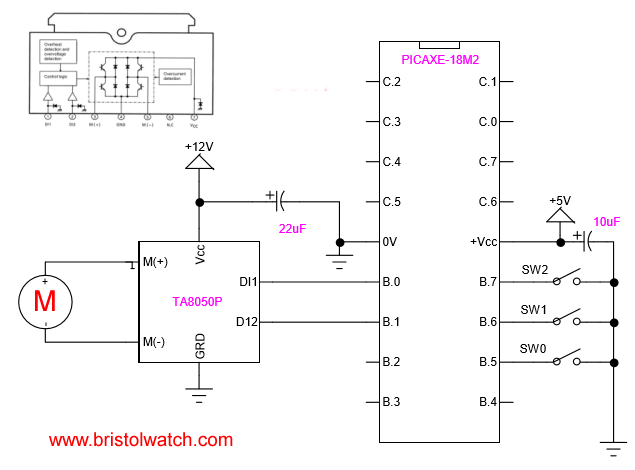
PICAXE-18M2 connected to TA8050P H-Bridge Motor Control
PICAXE-18M2 Controls TA8050P H-Bridge Motor Controller
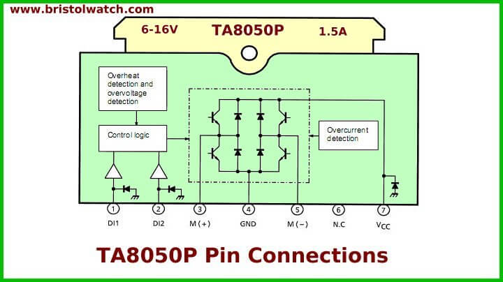
Also see TA8050P specification sheet and Arduino with TA8050 Motor Controller. Also TA8050P internal diagram.
Here we are using a PICAXE-18M2 microcontroller to operate a Toshiba TA8050P H-bridge. While built on a PIC ship related to PIC16F628A it has a built in basic interpreter. These functions while far easier to use than assembly still allow easy low level programming. Like Arduino direct access IO ports, one has the same direct port access for speed and ease of connecting hardware.
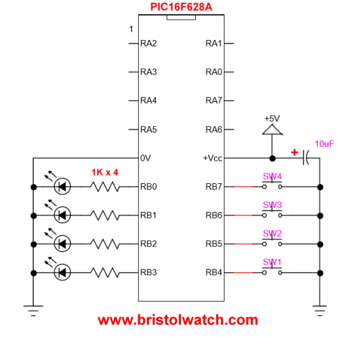
In fact the PICAXE-18M2 is the electrical equivalent pin wise to the PIC16F628A and related PIC microcontrollers. We have full access to all 16 IO pins with the exception C.5 is input only as is the PA5 on the PIC16F628A. PORTB is B.0 to B.7 while PORTA is C.0 to C.7. Don't ask me why they designated PORTA as PORTC.
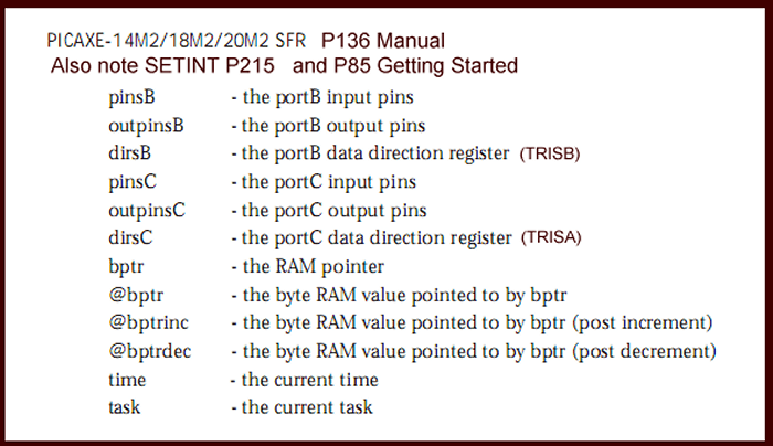
PICAXE Port register definitions.
As shown above each hard PORT has three registers each and all can be written to or read. These are all 8-bit register labeled 0 (LSB) and 7 (MSB). Registers dirsB (PORTB)and dirsC (PORTC) are the direction registers that determines if a IO pin is input or output. A "1" makes the corresponding pin an INPUT while a "0" makes the pin an OUTPUT. Note the following:
"let dirsB = %00001111 ; B.7-B.4 (MSBs) input, B.3-B.0 (LSBs) outputs
Like other PIC chips the PICAXE has internal pullup resistors on PORTB and operates as follows where a "1" in a corresponding bit turns on the internal pullup resistor:
pullup on ; enable pullups PORTB
pullup %11110000 ; pullups on B.7 - B.4
As a general rule because we often have multiple devices attached to a PORT we use a bitwise ANDs (& symbol) to CLEAR bits (change to 0) and a bitwise OR (| symbol) to SET bits (change to 1). Note this example:
let pinsB = pinsB & 0xF0 ; B.0 - B.3 output off
This statement that used I think 2 bytes read the value of PORTB then performed a bitwise AND with 0xF0 which is hexadecimal for binary %11110000, then stored it back to PORTB. Anything ANDed with 0 is zero while anything ANDed with 1 is unchanged. The 4 MSBs (B.7-B.4) of PORTB are my input switches which are not changed, the 4 LSBs (B.3-B.0) are Os grounding the output pins and turning off the attacked H-bridge or whatever. Note the following:
let pinsB = pinsB | %00000001 ; same as "high B.0"
Here we used a bitwise OR (anything ORed with 1 is 1, anything ORed with 0 is unchanged) to set B.0 to 1 which outputs 5V on pin 6 of the PICAXE-18M2, but changes nothing else on the other pins. This useful for changing more than 1 pin at a time, but with a single pin use "high B.0".
Wire up any 2 input H-bridge as shown above and one can forward, reverse, or stop a motor with three switches. Here is another H-Bridge Motor Control Diagram that will work. The entire program used in the video follows:
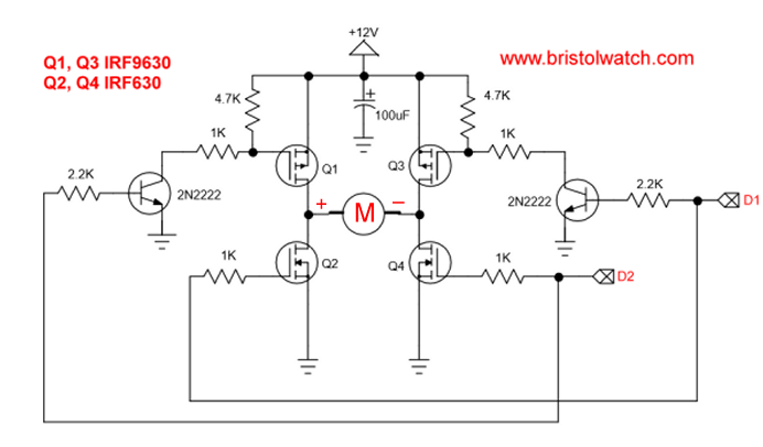
; setfreq m4  ; All M2 parts internal k31,
; k250, k500, m1, m2, m4, m8,m16,m32
; Use terminal at 9600 at 8 mHz
; if using 4 mHz set terminal 4800

let dirsB = %00001111 ; PB0-PB3 output, PB4-PB7 input
pullup on ; enable pullups PORTB
pullup %11110000 ; pullup B.7 - B.4

let pinsB = pinsB & 0xF0 ; outputs off

symbol SW0 = pinB.5 ; all HIGH when open
symbol SW1 = pinB.6
symbol SW2 = pinB.7

main:
if SW0 = 0 then goto OFF1 ;endif
if SW1 = 0 then goto REV1 ;endif
if SW2 = 0 then goto FOR1 ;endif
goto main


REV1:
let pinsB = pinsB & 0xF0 ; motor off
pause 500
; let pinsB = pinsB | %00000001 ; motor on
high B.0
goto main

FOR1:
let pinsB = pinsB & 0xF0 ; motor off
pause 500
;let pinsB = pinsB | %00000010 ; motor on
high B.1
goto main

OFF1:
let pinsB = pinsB & 0xF0 ; motor off
pause 500
goto main
- Microchip PIC related videos:
- How to Use K150 PIC Programmer
- Microchip PIC16F628A Basic H-Bridge Motor Control
- Microchip PIC16F628A Counts BCD on 8 LEDs
- PIC16F84A Operates H-Bridge Motor Control
- PIC16F84A Operates MOSFET H-Bridge
- Using Velleman K8048 PIC Development Board
- Microchip PIC16F84A H-Bridge Motor Control
- Microchip PIC16F628A Basic H-Bridge Motor Control
- PICAXE Operates H-Bridge Motor Controller
- PICAXE Micorcontroller Controls Motor Speed - Direction
- PICAXE Projects
- Arduino Port Registers Revisited
- Digispark ATtiny85 with MCP23016 GPIO Expander
- Safely Build Program a H-Bridge
- Build H-Bridge Motor Control Without Fireworks
- MOSFET H-Bridge for Arduino 2
- Web Master
- Gen. Electronics
- YouTube Channel
- Arduino Projects
- Raspberry Pi & Linux
- PIC18F2550 in C
- PIC16F628A Assembly
- PICAXE Projects
Web site Copyright Lewis Loflin, All rights reserved.
If using this material on another site, please provide a link back to my site.