
Fig. 1
Click here for larger image.
Microchip PIC16F628 Assembly Code Programs Tutorial
by Lewis Loflin
Follow @Lewis90068157
In this section we will explore how to use the Microchip PIC mostly the 16F628A. While the previous section on the PIC18F2550 was written in C, here I'll use only assembly language.
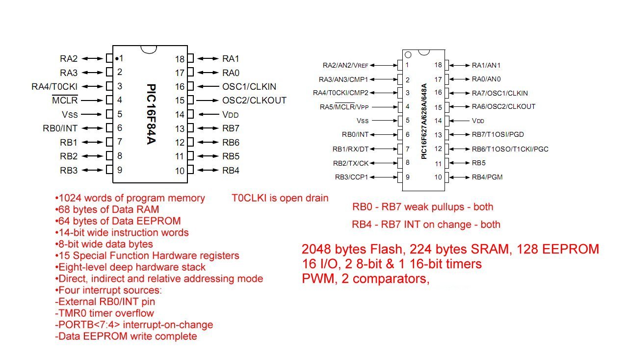
On issues with TMR0, PORTB pullups, and interrupts the PIC16F628A is similar to the PIC16F84A.
This is built on earlier sections. See the following
- Introduction PIC12F683 Programming Circuits Tutorial
- Operate PIC16F84A TMR0 from RA4/T0CKI Pulse Input
- Toggle ON-OFF LED Based on External Interrupt
- Programming PIC16F84A-PIC16f628a Timers by Example
- Programming PIC16F84A-PIC16F628A TMR0 Interrupts
- Programming PIC16F84A Software Delay Routines by Example
PIC16F628A Digikey $2.74, Mouser $3.07, and $2 ea. Ebay. For pin connections and specs see image pic16f84a_pic16f628a.jpg. The PIC6F628A is a major upgrade to the PIC16F84A and more complex. For the novice is harder to learn.
Related YouTube Video: Home Built PIC Dev. Board.
Why assembly? It's produces fast and efficient coding over C for basic functions related to electronics control. This enables one to really access the powerful features of the PIC. As a RISC processor it has only 35 instructions to learn. They operate at the register and bit levels.
These were developed using MPLAB v8.92.
The projects concentrate on using the PIC16F628A that has the following features:
- 2048 bytes of flash RAM
- 224 bytes of data SRAM
- 16 programmable IO pins
- Three timers, two 8-bit and one 16-bit
- Only 35 single work instructions
- Pulse width modulation unit.
- Internal PORTB pull ups.
- Operation to 20 mHz
And so much more. While 2048 bytes may not sound like much, most of the demos used more than 75 bytes! That includes operating a bipolar stepper motor and reading an external analog to digital converter, which the 16F628A lacks. The 12F683 has 4 ADC channels, but only six IO pins. (8 pins total.)
PICs utilize the Harvard architecture in which instructions and data operate on separate sources, which simplifies timing and microcircuit design. While they can be programmed in circuit, I used a separate programmer and a ZIP socket in my home built development board.
External Crystal or Internal RC Oscillator?
The PIC16F628A has an internal 4 mHz. and 38kHz. oscillators meaning no need for an external crystal. But there some issues to discuss. Oscillator base or Fosc is divided by 4 to create the execution clock cycle. Most commands use 1 clock cycle, branches use 2 clock cycles.
A 16 megahertz crystal is divided by 4 to 4mHz. The cycle time is 0.250 uSecs or 250 nano seconds. For a 4mHz crystal, 1 uSec.
There is a choice for a 4mHz internal oscillator, 38kHz internal oscillator, or faster 16mHz, etc. external crystal, etc.
With the __CONFIG line one has the following choices:
Use _HS_OSC for a 16 mHz ext crystal.
Use _XT_OSC for 4 mHz ext crystal. Page 95 in spec sheet.
Use _FOSC_INTOSCIO for Internal 4 mHz osc and no ext reset, MCLR pin RA5 is input only.
But to use 4mHz or the internal 38KhZ oscillator the PCON register (power control register bank 1, 8Fh) bit 3 must be set 1 = 4mHz, or 0 = 38 kHz.
Note PCON bit 3 can be cahnged under software control to switch to low-power operation.
This defaults to 38kHz and was fit to figure out. Most PIC spec sheets are poorly written for the novice. 38kHz is used for low power applications.
Software Delay Loops
The program below covers software delay loops. Whether using internal or external Fosc some tuning is desired. Note the following two short code snippets.
The first is a simple toggle LED function using XORWF that loads the W register with 2, then XORs W with PORTB bit 1 (RB1). This toggles the state of the LED on RB1 with every cycle, 2 cycles creates a complete square wave.
Each cycle or iteration jumps to the 1mSec. delay routine. 1,000 iterations creates a 500Hz square wave measured on a frequency country. This assumes a 4mHz Fosc clock frequency that when divided by 4 is 1uSec.
main

	movlw 0x02
	xorwf PORTB, f
	call delay1ms
	goto $-3

goto main

;**************************	;Delay routine.
; Calculating a 1mSec delay. 4mHz is divided by 4
; At 4mHz / 4 = 1uSec. ;  1uSec. * 1000 = 1 mSec.
; GOTO uses 2 cycles, DECFSZ 1 cycle = 3 cycles or 3uSec.
; 3 * ~83 * 4 = ~ 1000uSec. or 1mSec.
; Adjust CNT2 for 500 Hz on RB1 LED.

; For 16mhz CNT1 = 0x07, CNT2 = 0xBC.

delay1ms
	; 4 mhz crystal
	movlw d'4'
	movwf CNT1
	movlw d'83' ; adjust for 500Hz test
	movwf CNT2
	decfsz CNT2, f
	goto $-1 ; count 82 * 3
	decfsz CNT1, f
	goto $-5
	return
;*********************************************
; Filename: 16F628A_PWM.asm
; Uses PIC16F628A
; Date: 13 Nov. 2013
; Author:  Lewis Loflin
; http://www.bristolwatch.com
; http://www.bristolwatch.com/PIC16F628A/a7.htm
; Delay routines based on 4 mHz Fosc / 4 = 1uSec.
; LED1 on RB1 blinks 1Hz, PWM LED on RB3 off to bright to off.
; PWM output PORTB, 3
;*******************************************

list      p=16f628A           ; list directive to define processor
#include <p16F628A.inc>      ; processor specific variable definitions
errorlevel  -302              ; suppress message 302 from list file

__CONFIG _CP_OFF & _LVP_OFF & _BOREN_OFF & _MCLRE_OFF & _WDT_OFF & _PWRTE_ON & _XT_OSC
; single line do not press return on keyboard.


; Use  _FOSC_INTOSCIO  for
; Internal 4 mHz osc and no ext reset, MCLR pin RA5 is input only.
; Internal RC OSC PCON bit 3 must be set
; 1 = 4mHz, 0 = 38 kHZ

; Use _HS_OSC for a 16 mHz ext crystal.
; Use _XT_OSC for 4 mHz ext crystal. Page 95 in spec sheet.


;-------------------------- counters
;*****[ Data Storage Reg's ]*****
	; Assign each reg. from Bank 0 RAM area.
	; total 96 bytes from 0x20 - 0x7F
	CBLOCK  0x20
	B0
	B1
	B2
	temp1
	temp2
	CNT1
	CNT2
	CNT3
	CNT4
	ENDC ; Conclude Bank 0 RAM assignments.


	ORG     0x000             ; processor reset vector
	goto    setup             ; go to beginning of program

setup ; init PIC16F628A

;************************************************************
	; PWM calculator www.micro-examples.com
	; 4 mHz. clock.
	; PR2 = %11111001 'Timer2 Module Period Register - Bank 1
	; rest bank 0
	; T2CON = %00000101
	; P52, Bits 6-3 postscaler, 0000 = 1:1
	; Bit 2 TMR2ON, 1 = ON, 0 = OFF
	; Bits 1-0 prescaler value 01 = 1:4
	; CCPR1L = %0  ' duty cycle 0-255
	; CCP1CON = %00001100  'CCP1 control register
	; Bits 3-0 CCP mode select, 110x =  PWM active high
	; Bits 5-4 PWM LSB
	; Bits 7-6 unused

	; Set for 1,000 Hz.
	BANKSEL 1 ; Bank 1
	MOVLW B'11111001'
	MOVWF PR2
	BANKSEL 0 ; Back Bank 0
	MOVLW B'00000101'
	MOVWF T2CON
	MOVLW 0 ; duty cycle
	MOVWF  CCPR1L ; duty cycle 0-255
	MOVLW B'00001100'
	MOVWF CCP1CON

;*************************************************************
	; Setup TRIS DDR register and PCON register, PORTB pull ups.
	BANKSEL OPTION_REG          ; Switch to Bank 1.
	MOVLW b'111111' ; input
	MOVWF TRISA ;
	MOVLW B'11110001'
	MOVWF TRISB
	; Setup PCON bit 3,
	; 1 = 4mHz, 0 = 48kHz
	MOVLW b'00001000'
	MOVWF PCON

	; pull ups
	BCF OPTION_REG, 7 ; turn on PU, 1 = off, 0 = on
	; pull ups disabled if pin is output.
	; No WPU individual pins as in PIC12F683

;*************************************************************
	; Voltage refernce moodule test.
	; Make sure +5V supply VDD is accurate.
	; VREF control VRCON 9Fh,  P69
	; Check TRISA bit = 1
	; 1. VREF=ON, RA2 out, high range, <3:0> = 0, VOUT = 1.25V
	; 2. VREF=ON, RA2 out, low range, <3:0> = 15, VOUT max = 3.125V
	movlw b'11101111' ; measure 3.125V on RA2
	movwf VRCON
	; bit 7 VREN, 1 = on, 0 = off
	; bit 6 VROE, 1 = ouput RA2, 0 = no output
	; bit 5 VRR,
	; 1 = low range VREF = (VR<3:0> / 24) * VDD
	; 0 = high range VREF = 1/4 * VDD + (VR<3:0>/ 32) * VDD
	; bit 4 XX
	; bits 3-0 = 0-15

	BANKSEL PORTB  ; Switch to Bank 0.
	MOVLW   0x07  ; comp off
	MOVWF   CMCON
	CLRF    PORTB

	goto main

main
; remaining code goes here

; Demo 1
; 1mSec. delay calibrate.
; Freq. counter attached to LED1 on RB1.
; Should measure 500Hz. Adjust CNT2 value
; if needed for 500Hz on LED1.
; 1 cycle generated every 2 interations.
; Uncomment following to measure freq.

;	movlw 0x02
;	xorwf PORTB, f
;	call delay1ms
;	goto $-3


; Demo 2
; CCPR1L is 8-bit PWM duty cycle reg. 0-255.
; RB3 is PWM output to LED2 to GRD.
; LED2 on pin RB3 goes from off to bright in steps.
; Clear PWM register CCPR1L, LED2 = OFF
; Flip state of LED1 RB1 with XORWF
; W = 50, call delay Wx10ms = 500mSec.
; 2 loops = 1 Hz. rate on LED1 RB1
; Every loop 20 ADDed to CCPR1L reg.
; LED2 gets brighter
; Every 1Hz 40 is ADDed to PWM CCPR1L
; Check STATUS bit C
; Exit loop if C = 1, C = 0 back aa
; Repeat until STATUS C bit = 1.
	clrf 	CCPR1L
aa	movlw 0x02
	xorwf PORTB, f
	movwf d'50'
	call Wx10ms ; LED ON 0.5 sec.
	movlw d'20'
	addwf CCPR1L, f
	btfss STATUS, C ; check carry
	goto aa

; CCPR1L is 8-bit PWM duty cycle reg. 0-255.
; RB3 is PWM output to LED2 to GRD.
; LED2 on pin RB3 goes from bright to off in steps.
; PWM register CCPR1L = 255, LED2 on RB3 is bright
; Flip state of LED1 RB1 with XORWF
; W = 50, call delay Wx10ms = 500mSec.
; 2 loops = 1 Hz. rate on LED1 on RB1
; Every loop 20 SUBed from PWM CCPR1L reg.
; LED2 get dimmer
; Every 1Hz 40 is SUBed from PWM CCPR1L
; Check STATUS bit C for borrow
; Exit loop if C = 0, C = 1 back  bb
; Repeat until STATUS C bit = 0.
	movlw d'255'
	movwf CCPR1L
bb	movlw 0x02
	xorwf PORTB, f
	movwf d'50'
	call Wx10ms ; LED ON 0.5 sec.
	movlw d'20'
	subwf CCPR1L, f
	btfsc STATUS, C ; check borrow
	goto bb

	goto	main

;**************************	;Delay routine.
; Calculating a 1mSec delay. 4mHz is divided by 4
; At 4mHz / 4 = 1uSec. ;  1uSec. * 1000 = 1 mSec.
; GOTO uses 2 cycles, DECFSZ 1 cycle = 3 cycles or 3uSec.
; 3 * ~83 * 4 = ~ 1000uSec. or 1mSec.

delay1ms
	; 4 mhz crystal
	movlw d'4'
	movwf CNT1
	movlw d'83' ; adjust for 500Hz test
	movwf CNT2
	decfsz CNT2, f
	goto $-1 ; count 82 * 3
	decfsz CNT1, f
	goto $-5
	return


delay10ms
	movlw d'10'
	goto $+2
Wx1ms	; W * 1mSec.
	movwf CNT3
	call delay1ms
	decfsz CNT3, f
	goto $-2
	return


Wx10ms	; W * 10mSec.
	movwf CNT4
	call delay10ms
	decfsz CNT4, f
	goto $-2
	return

	END  ; directive 'end of program'
See How I got into Electronics

- You Tube Videos for this Series
- Home Built PIC Development Board
- PIC16F628 PIC Using Rotary Encoder to Operate Stepper Motor
- Using a Serial ADC with PIC16F628
- Calculating Pulse-Width Modulation with a PIC
- PIC16F84A-628A Hardware Time Delays
- PIC16F84A-628A Timer Interrupt Delays
- PIC16F84A-628A Pullups and Interrupts
- PIC16F84A-628A Hardware Interrupts Tutorial
- Projects using PIC16F628A:
- Exploring the Microchip PIC in Assembly
- Using a Microchip PIC with TLC548 Serial ADC
- Controlling PIC Pulse Width Modulation with a Serial ADC
- Using TMR0 on a PIC with Interrupts
- External Clock Crystal with PIC16F628 TMR1 Generates Interrupt
- PIC Using Rotary Encoder to Operate Stepper Motor
- PIC16F628 Pulse Width Modulation Controls Brightness of LED
- Another way to Turn On-Off PWM in a PIC
- Programming PIC16F84A-PIC16F628A Interrupts by Example
- PIC16F84A-PIC16F628A Pull Up Resistors with Interrupts
- Programming PIC16F84A-PIC16f628a Timers by Example
- Programming PIC16F84A-PIC16F628A TMR0 Interrupts
- Programming PIC16F84A Software Delay Routines by Example
Web site Copyright Lewis Loflin, All rights reserved.
If using this material on another site, please provide a link back to my site.