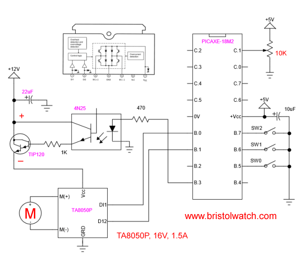
PICAXE microcontroller with TA8050P H-Bridge
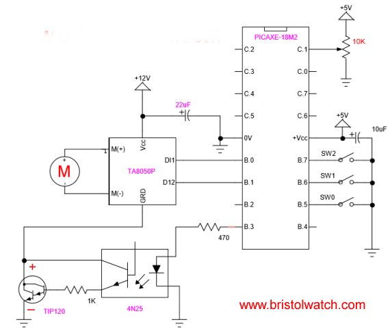
Alternative schematic for PICAXE and TA8050P speed control works the same way - observe polarity on transistor!
Here we are going beyond PICAXE Controls TA8050P H-Bridge Motor with PORT Programming to not only stopping and changing direction of motor rotation, but to also control rotation in either direction. I'll cover only the speed control part here.
In the schematic above I've inserted an OPTO-coupler transistor circuit into the Vcc or GRD side of the in this case TA8050P h-bridge motor control. Reading the value of a 10K potentiometer on pin C.1 through the internal analog-digital converter I return a 10-bit value used the set the duty cycle on the PWM out on B.3. For more on PWM see Pulse-Width Modulation Tutorial.
Also see PIC12F683 Programming Circuits Tutorial
For example with a LED connected to B.3 when the potentiometer is adjusted the brightness of the LED varies based on position. The programming for this is very simple:
#picaxe 18m2 ; type chip used

;setfreq m4 ; All M2 parts internal k31,
; k250, k500, m1, m2, m4, m8,m16,m32

symbol control = C.1
symbol val = w0 ; word (16-bit) user variable
symbol pwmPin = B.3 ; use only B.3 or B.6

init: ; setup PWM
pwmout pwmdiv4, pwmPin, 124, 1023

loop:
; readadc returns 8 MSB if used
readadc10 control, val  ; get 10-bit value
; read 10-bit ADC into variable w0

pwmduty pwmPin, val  ; set pwm duty
goto loop  ; loop back to start
That's the whole program which takes about 47 bytes. Here is the code integrating the earlier direction control only with speed control though the TIP120 Darlington.
- PICAXE Related:
- Tutorial: Programming-Using PICAXE-18M2 Microcontroller
- How to setup PICAXE Pulse Width Modulation
- PICAXE TA8050P H-Bridge with Motor Control
- PICAXE TA8050P H-Bridge with Motor Speed Control
- PICAXE-18M2 Uses MCP23016 GPIO Expander
Truth Table:
B.0 - 1; B.1 - 0 forward;
B.0 - 0; B.1 - 1 reverse;
B.0 - 0; B.1 - 0 stop.
Main program starts below:
; setfreq m4  ; All M2 parts internal k31,
; k250, k500, m1, m2, m4, m8,m16,m32
; Use terminal at 9600 at 8 mHz
; if using 4 mHz set terminal 4800

; all HIGH when open
symbol SW0 = pinB.5
symbol SW1 = pinB.6
symbol SW2 = pinB.7

symbol control = C.1
symbol val = w0 ; word (16-bit) user variable
symbol pwmPin = B.3

init:
pwmout pwmdiv16, B.3, 124, 1023

let dirsB = %00001111 ; PB0-PB3 output

let pinsB = pinsB & 0xF0 ; all pins off

pullup on        ;enable pullups
pullup %11110000 ; pullup only on PB5-PB7

loop:
if SW1 = 0 then goto REV1 ;endif
if SW2 = 0 then goto FOR1 ;endif
if SW0 = 0 then goto STOP1

readadc10 control, val
; read 10-bit ADC into variable w0

pwmduty pwmPin, val  ; set pwm duty
pause 10 ; wait 10mS
goto loop

REV1: ; reverse
let pinsB = pinsB & 0xF0 ; motor off
pause 500
let pinsB = pinsB | %00000001
; motor on B.0 HIGH, B.1 LOW
goto main

FOR1: ; forward
let pinsB = pinsB & 0xF0 ; motor off
pause 500
let pinsB = pinsB | %00000010
; motor on B.1 HIGH, B.0 LOW
goto main

STOP1: ; stop
let pinsB = pinsB & 0xF0
; motor off B.0 and B.1 LOW
pause 500
goto main
; end program
Related: Introduction PIC12F683 Programming Circuits Tutorial
See How I got into Electronics
- Arduino Port Registers Revisited
- Digispark ATtiny85 with MCP23016 GPIO Expander
- Safely Build Program a H-Bridge
- Build H-Bridge Motor Control Without Fireworks
- MOSFET H-Bridge for Arduino 2
- PICAXE Projects
- YouTube videos:
- Simple Power Distribution for Prototype Board
- Program Arduino Ports for Speed and Control
- Digispark ATtiny85 with GPIO Expansion
- Safely Program H-Bridge Motor Controller
- Build H-Bridge Motor Control without Fireworks
- MOSFET H-Bridge for Arduino 2
- Arduino Projects Revisited Revised
- Programming ADS1115 4-Channel I2C ADC with Arduino
- Arduino uses ADS1115 with TMP37 to Measure Temperature
- Connect Arduino to I2C Liquid Crystal Display
- Arduino Reads Temperature Sensor Displays Temperature on LCD Display
- Arduino with MCP4725 12-bit Digital-to-Analog Converter Demo
- Videos
- Arduino with ADS1115 4-Channel 16-bit Analog-to-Digital Converter
- Arduino with MCP4725 12-Bit DAC
- Constant Current Circuits with the LM334
- LM317 Constant Current Source Circuits
- Introduction Hall Effect Switches, Sensors, and Circuits
- Microchip PIC related videos:
- How to Use K150 PIC Programmer
- Microchip PIC16F628A Basic H-Bridge Motor Control
- Microchip PIC16F628A Counts BCD on 8 LEDs
- PIC16F84A Operates H-Bridge Motor Control
- PIC16F84A Operates MOSFET H-Bridge
- Using Velleman K8048 PIC Development Board
- Microchip PIC16F84A H-Bridge Motor Control
- Microchip PIC16F628A Basic H-Bridge Motor Control
- PICAXE Operates H-Bridge Motor Controller
- PICAXE Micorcontroller Controls Motor Speed - Direction
- PICAXE Projects
- Arduino Port Registers Revisited
- Digispark ATtiny85 with MCP23016 GPIO Expander
- Safely Build Program a H-Bridge
- Build H-Bridge Motor Control Without Fireworks
- MOSFET H-Bridge for Arduino 2
- Web Master
- Gen. Electronics
- YouTube Channel
- Arduino Projects
- Raspberry Pi & Linux
- PIC18F2550 in C
- PIC16F628A Assembly
- PICAXE Projects
Web site Copyright Lewis Loflin, All rights reserved.
If using this material on another site, please provide a link back to my site.