
PICAXE 18M2 Microcontroller Circuits
The PICAXE series of micro-controllers rank as the easiest and most cost effective way to use Microchip processors. I wanted an easier and less expensive way to introduce my students to the "PIC" micro-controller. Here I hope to get those starting out past poorly written literature and lack of simple working code examples.
- Related to figure 1:
- Connecting the Picaxe to a H-Bridge DC Motor Control
I've used the Arduino-Atmga168 series of for a few years and have produced a number of circuits around them. Its programming is based on C++ which can be difficult to learn without a formal class in C/C++. Second it follows the C++ convention of hiding the actual hardware from the programmer. This makes understanding the underlying hardware nearly impossible. While having a number of libraries to do any number of tasks, that too hides the underlying processes from the programmer.
The PICAXE gets around most of those problems. The PICAXE uses a form of basic similar to the Parallax series of micro-controllers at a cost of $6-$7 versus $40-$50 for the Basic Stamp series. PICAXE basic is free while PicBasic Pro and others cost hundreds of dollars. Compared to the Atmega168-Arduino it has some weaknesses, but does other things much better.
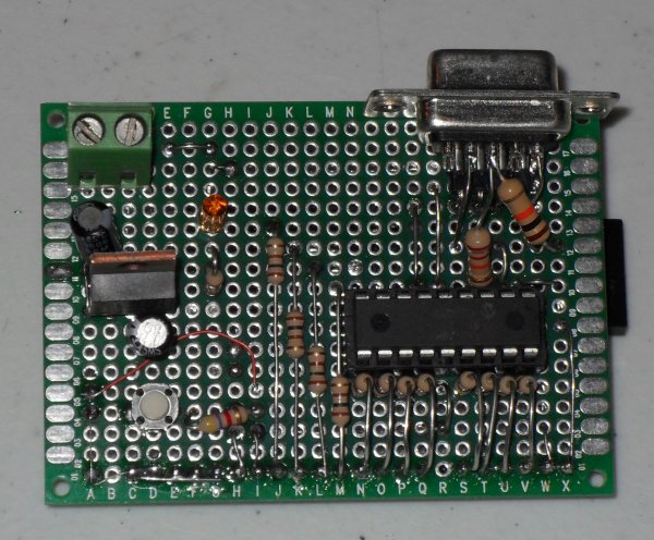
My teaching philosophy is to learn the "basics" and build upon them. So we will explore how to connect electronic circuits to the PICAXE to learn electronics while basic programming is a bonus. I'll explain how the code works and present a number of simple working examples. Pictured above is the schematic to the test board I constructed based on the PICAXE 18M2 part.
PICAXE has several different types and I chose the middle unit to work with. While lacking some features of their more advanced chips, I'll demonstrate how to work around them. Click to view an actual picture of my test board.
For more information on their other PICAXE "chips" visit their website at www.picaxe.com. Their literature and software are free for download. For more information on the 18M2 we will be using here see PICAXE-18M2 Information.
For more information on the Atmega168-Arduino see my ATMEGA168 Arduino Micro Controller Projects page. In many cases I will compare the PICAXE to Arduino.
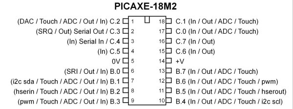
Fig. 2 PICAXE 18M2.
Pictured above is the 18M2 chip. Based on the Microchip PIC16(L)F1826. It has 2048 bytes of program memory (flash RAM), 256 byes of static RAM, 256 bytes of EEPROM, and 16 I/O pins that can be configured as shown above. The I/O is configured in two 8-bit ports known as PORTB and PORTC. Each individual bit in each port can be configured individually.
In practical terms pins C.3 and C.4 are reserved for serial I/O while C.5 is input only. Because the PICAXE command reference is vague and frustrating to understand, I'll cover issues I think are relevant to getting started. Don't let the small amount of program memory fool you, it seems the basic interpreter is contained within the "chip" already so the program itself takes up little memory.
Some Tips to Get Started
The best way to learn this is to walk through the various small programs I've written. Here are some tips and advice:
1) In the above board diagram I'd suggest using 220 ohm resistors between most of the PICAXE I/O pins and whatever they are connected to. Using these should protect the chip from damage in case one miss-wires the connections.
2) Trying to use a RS232 to TTL converter to program the chip won't work. One has to use the 22k and 10k resistors as above with a real serial port or USB to RS232 adaptor cable. Or one can buy the cable from PICAXE. Also do not use a PIC programmer because one can destroy the internal boot loader program and PICAXE won't replace it. Also running out and buying a blank PIC16LF1826 won't work either.
3) The PICAXE M2 series of chips will operate under 2-volts or with two 1.5-volt AA batteries. Here I assume one is using a standard 5-volt power supply because many of the parts I use in the demos won't operate below 5-volts. +Vcc (or VDD on manufacturers spec sheets) is always +5-volts and ground (also called VSS) is always negative.
4) Comments are important in order to make sense of the program later on. I often develop small programs then cut/paste into larger programs. To do a single line comment use ";". To do a multi-line comment use #rem and #endrem. (This is the same as /* and */ in C++.) The compiler ignores all comments. Unlike C type compilers ";" is not used to terminate a line but the same manner as "//" which is a comment.
5) The PICAXE compiler is not case sensitive. So to the compiler "HIGH is the same as "High" is the same as "high". C++ throws a fit with this.
6) The PICAXE M2 series of chips can operate up to 32 mHz (million cycles per second) and can be changed under software control. While the unit defaults to 4 mHz, I often include this line on most of my programs:
setfreq m4 ; All M2 parts internal k31, k250, k500, m1, m2, m4, m8,m16,m32
To set the internal resonator to 16 mHz for example: setfreq m16. Note that changing the CPU speed from the default 4 mHz will effect other time sensitive commands such as "pause".
I also include the following and any of them can be commented out if not needed:
#picaxe 18m2 ; type chip used
#com4 ; serial port to use if you know it
#terminal 4800 ; set baud rate serial terminal and open (default).
7) The command "symbol" (often used at the top of the page) will be used extensively in the same manner as "#define" on the Arduino and other "C" type compilers. For example the line "symbol LED1 = C.0" means anywhere in the program I use LED1 the compiler will know this is portc bit 0 or electrical pin 17 where I assume one has an LED properly attached. Note the PICAXE compiler will use "#define" but has a differing meaning than the "symbol" command.
Picaxe Micro-controller Projects!
The PICAXE series of micro-controllers rank as the easiest and most cost effective way to use Microchip processors. I wanted an easier and less expensive way to introduce my students to the "PIC" micro-controller. Here I hope to get those starting out past poorly written literature and lack of simple working code examples.
- PICAXE Related videos:
- My YouTube Channel
- Tutorial: Programming-Using PICAXE-18M2 Microcontroller
- How to setup PICAXE Pulse Width Modulation
- PICAXE TA8050P H-Bridge with Motor Control
- PICAXE TA8050P H-Bridge with Motor Speed Control
- PICAXE-18M2 Uses MCP23016 GPIO Expander
- PICAXE-18M2 Operates MOSFET H-Bridge
- PICAXE Motor speed control Old poor quality video.
- Solar Panel Charge Controller Using PICAXE Microcontroller
- Exploring the PICAXE Micro-Controller
- Understanding Micro-Controller Input/Output Ports
- Using the 74HC165 Shift Register with the PICAXE Micro-Controller
- Connecting the 74HC595 Shift Register to PICAXE Micro-controller
- Using 7-Segment Displays with the PICAXE Micro-Controller
- Potentiometers and Analog-to-Digital Conversion with the PICAXE
- Pulse-Width Modulation Motor Speed Control and the PICAXE Micro-Controller
- Connecting the PICAXE to the DS1307 Real Time Clock
- Connecting the PICAXE to an External EEPROM (24LC08)
- Connecting a Servo to a PICAXE
- Connecting the TLC548 to the PICAXE
- Connecting the Ad5220 Digital Potentiometer to the PICAXE
See How I got into Electronics
