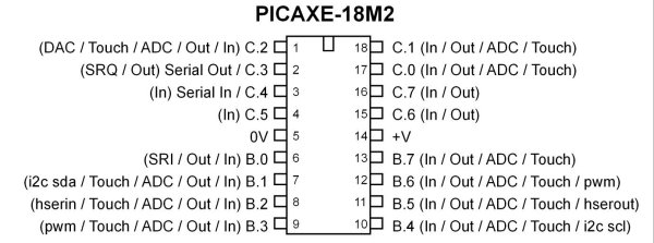
Fig. 1 PICAXE 18M2.
PICAXE 18M2 Controls 74HC164 Shift Register
The object of this tutorial is to introduce the student and hobbyist to shift registers and using code with the PICAXE micro-controller. We will also look at how to connect groups of 8 LEDs in both common anode/cathode configurations and how to switch them on/off as a group using external transistors.
This demonstration will use 8 light emitting diodes (LEDs) to count in binary from 0 to 255. This will require eight bits or one byte. How this count is displayed depends on how the LEDs are connected and how the bits are shifted into the shift register.
To see a wiring diagram of the board I built and used in the demo see Exploring the PICAXE Micro-Controller.
Fig. 2 internal block diagram of the 74HC164.
Fig. 2 above shows a typical internal block diagram of a eight-bit shift register. In the case of the 74HC164 we have eight clocked "D" type flip-flops with common clock line (CP) and common reset line (MR NOT) that will set outputs Q0 - Q7 to all LOW or binary 0. Note in the electrical sense a HIGH or binary 1 will output (source) +5-volts while a binary 0 will switch (sink) the pin to ground.
For more on sink/source in regards to digital circuits see Understanding Micro-Controller Input/Output Ports
The 74HC164 8-Bit Serial-In - Parallel-Out Serial Shift Register has three inputs:
- Input A-B (pins 1, 2) is for data bit to be shifted in. They can be tied together or the one not used ties to +Vcc.
- CP or clock pin 8 data is shifted into the 8-bit register during the positive going transition of clock pulse. That is, whatever the state of input A-B will be shift one-bit right during each clock cycle and will continue to be shifted right during each consecutive pulse.
- Clear (pin 9) is independent of the clock and when taken LOW (0 volts), Q0 - Q7 will all go LOW (ground) on the corresponding output pin. This pin must be initialized/held HIGH for the register to operate.
Fig. 3 electrical connections to the 74HC164.
Connecting to the 74HC164
Now we must decide the physical electrical connections between the PICAXE, the 74HC164 and the LEDs. This will determine how the software will operate the system. Each pin (Q0 - Q7) on the 74HC164 will directly drive an LED.
The electrical connections between the 74HC164 and the PICAXE 18M2 are as follows:
74HC164 pins 1, 2 (A-B) are connected to pin 15 (C.6) on the PICAXE;
74HC164 pin 8 (CP or CLK) is connected to pin 16 (C.7) on the PICAXE;
74HC164 pin 9 (MR) is connected to pin 1 (C.2) on the PICAXE.
Now it's time to decide how to connect the eight LEDs to the shift register. There are two main configurations to consider and the one being used will determine how the program is written. Note these configurations can also be used for seven-segment LED displays as well which are simply eight LEDs arranged in the pattern of an "8" plus decimal point.
Here I'll only use the common cathode configuration for LEDs while on a separate page we'll use common anode for an 7-segment LED display.
Fig. 4 common cathode configuration.
Above is the common cathode configuration. Remember an LED is still a diode with the arrow pointing to the negative side and away from the positive side. In this case all eight cathodes are tied to GND while the anode side of each is connected to Q0 - Q7. This assumes the binary count will be from right to left arranged and labeled as shown above. At the end of eight clock cycles bit 0 will be at Q7 (connected to LED7) while bit 7 will be at Q0 (connected to LED0).
Fig. 5 common cathode configuration with blanking transistor.
The second version adds a minor modification of a blanking transistor. Connected to pin 18 (C.1) a HIGH will turn the LEDs on and a LOW off. This is useful for turning off the LEDs while the bits are shifted into the register eliminating flicker. Q1 is a general purpose NPN transistor such as a 2N2222.
The Software
The center of the program is the bit-shift code as follows:
     ; begin bit shift routine
     for i = 0 to 7
     temp = val & %00000001
     ; mask bit 0 using bitwise AND
     if temp = 1 then HIGH Bit_out
     else LOW Bit_out
     endif
     pulsout CLK,1 ; clock bit into register
     val = val / 2 ; shift bits one place right
     next i
     ; end bit shift routine
There is no "shift left" or "shift right" commands with the PICAXE. Dividing or multiplying by 2, 4, etc. does the same thing. A bitwise AND determines the state of the individual bit. That state sets or clears Bit_out then the command pulsout shifts the bit into the register.
The pulsout pin,time command generates a pulse of length time on a pin. If the output is initially low, the pulse will be high, and vice versa. This command automatically configures the pin as an output. In most cases I would initialize the pin myself so we start with a known state. See page 161 of the PICAXE Manual 2 Basic Commands.
The units of time are as follows and depends on setfreq command:
4MHz - 10us unit
8MHz - 5us unit
16MHz - 2.5us unit
32MHz - 1.25us unit
Example:
LOW B.1 ; set initial state to LOW
main:
pulsout B.1,150 ; send a 1.50ms HIGH pulse out of pin B.1 based on 10us unit
pause 20 ; pause 20 ms
goto main ; loop back to main
As far as least significant bit (LSB or bit 0) first or most significant bit (MSB or bit 7) first is up to software and electrical connections on the output. Here I used LSB first.
Fig. 6 multi digit LED display module.
The following section of code turns the LEDs on/off and allows one to view them after the sifting is completed. In this case I used the circuit in Fig. 5. This kind of switching is useful for activating individual digits in 7-segment LED display sticks such as above.
   HIGH LEDCON  ; LEDs on
   pause 400  ; leave display on to view
   LOW LEDCON  ; LEDs off
Main Program
#picaxe 18m2 ; type chip used
; set internal frequency of PICAXE to 4 mHz.
setfreq m4
; All M2 - k31, k250, k500, m1, m2, m4, m8,m16,m32

symbol val = b0 ; user variables
symbol temp = b1
symbol j =b2
symbol i = b3

symbol Bit_out = C.6
symbol CLK = C.7
symbol CLR = C.2
symbol LEDCON = C.1
; turns LEDs off/on if needed.

HIGH CLR ; set clear to HIGH or +5-volts
LOW CLK


main: ; begin main loop

pulsout CLR,10
; clear shift register, could be left out

for j = 0 to 255 ; count 0 to 255 in binary

     val = j  ; count to be shifted into 74HC164

     ; begin bit shift routine
     for i = 0 to 7
     temp = val & %00000001
     ; mask bit 0 using bitwise AND
     if temp = 1 then HIGH Bit_out
     else LOW Bit_out
     endif
     pulsout CLK,1 ; clock bit into register
     val = val / 2 ; shift bits one place right
     next i
     ; end bit shift routine

   HIGH LEDCON  ; LEDs on
   pause 400  ; leave display on to view
   LOW LEDCON  ; LEDs off

next j ; next count

goto main
Fig. 7 common anode configuration.
Fig. 8 common anode configuration with blanking transistor.
Figures 7 and 8 above illustrates the electrical connections for a common anode configuration. In this case I must invert the bit pattern into the 74HC164. The modified bit shift code is as follows:
     ; begin bit shift routine
     for i = 0 to 7
     temp = val & %00000001
     ; mask bit 0 using bitwise AND
     if temp = 1 then LOW Bit_out
     else HIGH Bit_out
     endif
     pulsout CLK,1 ; clock bit into register
     val = val / 2 ; shift bits one place right
     next i
     ; end bit shift routine
Because the use of a PNP transistor requires a LOW to turn the LEDs on:
   LOW LEDCON  ; LEDs on
   pause 400  ; leave display on to view
   HIGH LEDCON  ; LEDs off
Picaxe Micro-controller Projects!
The PICAXE series of micro-controllers rank as the easiest and most cost effective way to use Microchip processors. I wanted an easier and less expensive way to introduce my students to the "PIC" micro-controller. Here I hope to get those starting out past poorly written literature and lack of simple working code examples.
- PICAXE Related videos Oct. 2016:
- Tutorial: Programming-Using PICAXE-18M2 Microcontroller
- How to setup PICAXE Pulse Width Modulation
- PICAXE TA8050P H-Bridge with Motor Control
- PICAXE TA8050P H-Bridge with Motor Speed Control
- PICAXE-18M2 Operates MOSFET H-Bridge
- PICAXE-18M2 Uses MCP23016 GPIO Expander
- Solar Panel Charge Controller Using PICAXE Microcontroller
- Exploring the PICAXE Micro-Controller
- Understanding Micro-Controller Input/Output Ports
- Using the 74HC165 Shift Register with the PICAXE Micro-Controller
- Connecting the 74HC595 Shift Register to PICAXE Micro-controller
- Using 7-Segment Displays with the PICAXE Micro-Controller
- Potentiometers and Analog-to-Digital Conversion with the PICAXE
- Pulse-Width Modulation Motor Speed Control and the PICAXE Micro-Controller
- Connecting the PICAXE to the DS1307 Real Time Clock
- Connecting the PICAXE to an External EEPROM (24LC08)
- Connecting a Servo to a PICAXE
- Connecting the TLC548 to the PICAXE
- Connecting the Ad5220 Digital Potentiometer to the PICAXE
See How I got into Electronics
