Introducing the BOLT PIC18F2550 Microcontroller Board
YouTube video: Connecting PIC18F2550 to Parallel LCD Display
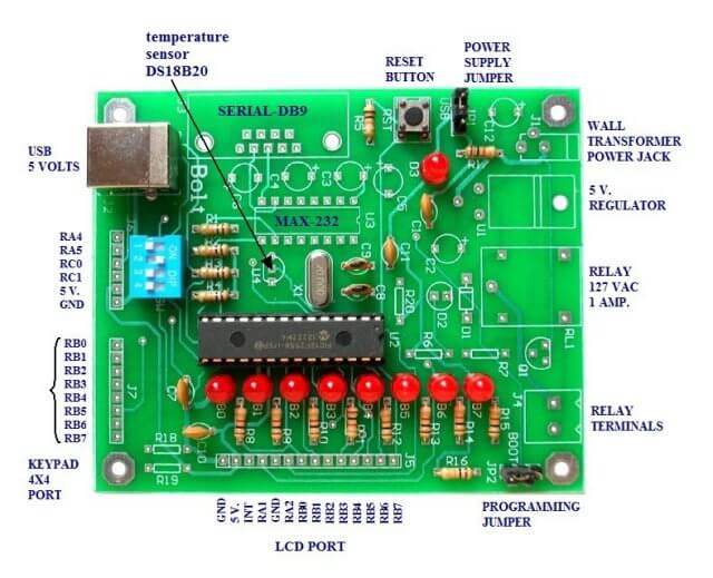
The BOLT microcontroller board utilizes the Microchip 18F2550 with built in USB capabilities. Utilizing a 2k 'boot loader' this leaves a great deal of flash RAM for C programming using MPLAB and the C18 compiler. The BOLT board comes in two versions. LITE which has the 18F2550, 8 LEDs for PORTB, four switches and a USB 2.0 port connection to a PC. Operating with a 20 mHz crystal, by use of internal multipliers operates at 48 mHz.
The full version has additional components including a relay, DS18B20 temperature sensor, RS232, etc. I went with the LITE version and added my own 90 degree header pins. The idea was to port over my Arduino projects to PIC C and learn how to program PICs. The BOLT comes with a lot of working examples in both assembly and C to gives the novice a place to start.
The system is powerful and inexpensive. With the LITE version at $15 which includes the 18F2550 it requires no external PIC programmer just a USB cable. This is right in the price range of an Arduino at three times the speed. While I'm using the 28-pin version, there's a 40-pin version with more I/O.
In comparison to Arduino I'd advise against using a PIC starting out without some electronics and C programming knowledge. One will also need to understand and setup MPLAB and understand the C18 compiler libraries which can be very valuable. While having a steeper learning curve than Arduino, it has greater versatility and potential.
The website for the BOLT is at http://www.puntoflotante.net/BOLT-SYSTEM.htm in Mexico. Be warned some of the notes in the examples are in Spanish but are fairly self-explanatory. I'm including ZIP files with the BOLT template which includes linker file and several H files for ADC, serial, and One-Wire. I also include most of the examples.
The PIC18F2550 has 32k of flash (2k used by boot loader), 2k of SRAM, 256 bytes of EEPROM, 24 I/O pins, 10 10-bit ADC channels, 2 PWM, USART, USB 2.0, etc. This is a RISC processor with 75 instructions and is 'optimized' for a C compiler.
The BOLT download page is at http://www.puntoflotante.net/BOLT-SYSTEM-DOWNLOAD.htm.
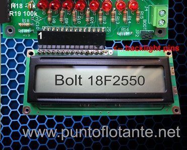
BOLT LITE with parallel LCD.
Below are a listing of my recent projects ported over mostly from my Arduino projects and some extra. I have my own code and H files depending on what hardware one wants to attach to the system. My LCD routines are for use with my serial 74164 LCD project from Arduino.
See Connect Arduino to LCD Display with 74164 Shift Register
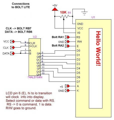
The board can use a common HD44780 directly connected to BOLT as shown above. Two resistors must be added: R18 is 1k and R19 is 100k. Notice the two backlight pins are disconnected. If one's display requires a backlight (mine did being blue) then solder a jumper from pin 15 (anode) to +5 volts (or pin 2) and pin 16 (cathode or K) to GND or pin 1.
In my case I soldered in a 5k potentiometer replacing R18/R19 to better adjust contrast.
There are two ways to connect the LCD display to BOLT either parallel as shown above or with my serial LCD project ported over from my Arduino project. Only one sub-routine has to be altered as shown below:
// shift data to 74164
void ssrWrite(char val)  {
	int j;
  for(j=1; j<=8; j++)  {   // shift out MSB first
    unsigned char  temp = val & 0x80; // MSB out first
    if (temp == 0x80) RB6 = HIGH; // RB6 DATA
    else RB6 = LOW;
	RB7 = HIGH;
	delay_us(20);
	RB7 = LOW;
    val = val << 1; // shift one place left
  }  // next j
}

// use for parallel LCD connection
void ssrWrite(char val)  {
	PORTB = val;
}
Timing could present a problem with slow devices such as a LCD display. The BOLT operates at 48 mHz while Arduino operates at 16 mHz. That was critical in particular with the initialization routine.
First got to 18F2550 BOLT PIC with Serial LCD Display will give an outline of system operation and uses all of the routines in the lewislcd.h file.
See Schematic Serial LCD(jpg file)
Don't use my lewislcd.h file with the 18F2550BOLT.h or the compiler will return errors. This is because both use some of the same definitions. Cut and paste the routines you want from mine, be sure to declare the functions above main() in the template.
18F2550BOLT.h has its own LCD routines for the parallel connection, the BOLT keypad, switches, etc.
Another issue is using the adc.h library from the C18 compiler with the BOLT-ADC.h library is adc.h must be above BOLT-ADC.h or the compiler will throw a fit. In MPLAB C18 Libraries (pdf file) it's a good idea to read about adc.h, timers.h, and pwm.h which I'll be making use of all of them.
See How I got into Electronics
Videos, Links, Downloads for the PIC18F2550 BOLT
- Introducing the BOLT PIC18F2550 Microcontroller Board
- PIC18F2550 BOLT with Serial LCD Display
- Using the MAX7219 with the 18F2550 Programs:
- MAX7219 Display Driver and a PIC Micro Controller
- MAX7219 Display Controller in the Non-Decode Mode with PIC
- Using TMR0 and Interrupts on the PIC18F2550
- YouTube Videos:
- My YouTube Channel
- MAX7219 display controller with 8X8 LED Matrix
- Programming the MAX7219 and 7-Segment Display
- Connecting PIC18F2550 to Parallel LCD Display
- Connecting PIC18F2550 to Serial LCD Displays
- Downloads:
- lewislcd.h My LCD H file
- Schematic Serial LCD
- BOLT_Template.zip
- Bolt Getting Started (pdf)

- Assembly language projects using PIC16F628:
- Exploring the Microchip PIC in Assembly
- Using a Microchip PIC with TLC548 Serial ADC
- Controlling PIC Pulse Width Modulation with a Serial ADC
- Using TMR0 on a PIC with Interrupts
- External Clock Crystal with PIC16F628 TMR1 Generates Interrupt
- PIC Using Rotary Encoder to Operate Stepper Motor
- PIC16F628 Pulse Width Modulation Controls Brightness of LED
- Another way to Turn On-Off PWM in a PIC
- TLC548 Serial ADC Spec. Sheet
Web site Copyright Lewis Loflin, All rights reserved.
If using this material on another site, please provide a link back to my site.