
Fig. 1
Click here for larger image.
Using PIC16F628A Timer and External Interrupts
by Lewis Loflin
Follow @Lewis90068157
The complete assembly file for this TMR0 demo is at TRM0_IRQ.asm
The complete assembly file for this EXT RB0 demo is at RB0_IRQ.asm
The Microchip PIC series of micro-controllers have a number of programmable interrupt sources. In this tutorial we will use 8-bit timer 0 (TMR0) to generates an interrupt every ~16.7mSec. which increments variable CNT (0x23) which at 59 counts toggle an LED ON-OFF on RB1.
Two toggles is 1 complete cycle. 60Hz. will produce a 30Hz square wave measured by a frequency counter. Many digital volt-ohm meters today have a frequency counter function.
With 4mHz crystal / 4 = 1uSec. TMR0 prescale set to 64 with the TMR0 register loaded 15 = 64 * 240 * 1uSec = 15.36mSec. The reciprocal of 15.36mSec. = 65.1 or 65. Thus counting 65 interrupts at 15.36mSec. each is ~1 second. Close enough.
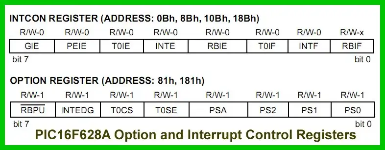
The 8-bit option register (81H BANK1) controls TMR0. It also controls (bit 6) the external interrupt at RB0 edge. The interrupt control register (INTCOM 0x0B BANK0) selects interrupt sources and has "flag" bits.
All hardware interrupts jump to "ORG 0x004". The interrupt service routine (ISR) is located here. The ISR can include jumps to subroutines and must be terminated with a "retfie" or return from interrupt command.
The INTCON and OPTION_REG register turns of TMR0 interrupts:
; setup TMR0 interrupts
	movlw b'10000111' ; internal clock, pos edge, prescale 256
	movwf OPTION_REG
	banksel INTCON ; bank 0
	bsf INTCON, GIE ; enable global interrupt
	bsf INTCON, PEIE ; enable all unmasked interrupts
	bsf INTCON, T0IE ; enable TMR0 interrupt
Note the following example ISR code:
	ORG     0x004 ; interrupt vector location
; isr code can go here or be located as a call subroutines

	movlw d'64' ; count 0-64 = 65 counts
	; approx 65 interrupts = ~1 sec. at 4 mHz crystal
	; 2 toggles = 1 cycle.
	; will measure ~0.5Hz square wave with 2 toggles
	; 32 or 33 interrupts measures ~1Hz square wave
	subwf CNT, w ; CNT = 64?
	btfss STATUS, Z ;
	goto $+4 ; no jump 4
	call toggle ; yes toggle LED RB1
	clrf CNT ; CNT = 0
	goto $+2
  	incf CNT ; CNT = CNT + 1
  	; start TMR0 again
  	movlw d'15' ; prelaod TMR0
  	movwf TMR0
	bcf INTCON, T0IF ; clear TMR0 interrupt flag
	retfie ; return from interrupt
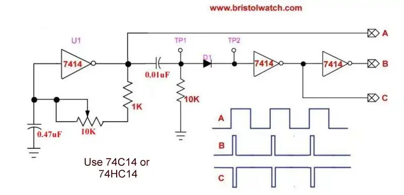
SN74HC14 based square wave generator with differentiator circuit.
The next section requires a square wave generator or source. This used the above setup one can build. See Simple Schmitt Trigger SN74HC14 Square Wave Generator
Connect either A or B to RB0 INT pin 6 on the PIC16F628A. Next turn on EXT interrupt. Note the following code snippet:
	; set up interrupts
	banksel OPTION_REG ; bank 1
	movlw b'01000000' ; bit 6 RB0 INT edge
	movwf OPTION_REG
	banksel INTCON ; bank 0
	bsf INTCON, GIE ; enable global interrupt
	bsf INTCON, PEIE ; enable all unmasked interrupts
	bsf INTCON, 4 ; RB0 int enable bit 4
Now note the ISR routine:
	ORG     0x004  ; interrupt vector location
	; isr code can go here
	; note: 2 toggles is 1 cycle on RB1 LED
	; 60 toggles = 30Hz

	; Test 1
	; movlw d'19' ; # of interrupts 20 (0-19)
	; 20 interrupts with 120Hz input = 3Hz sq. wave
	; 120Hz / (2 * (19 + 1)) = 3Hz output

	; Test 2
	movlw d'29' ; # of interrupts 30 (0-29)
	; 30 interrupts with 60Hz = 1Hz output
	; 60Hz / (2 * (29 + 2) = 1Hz

	subwf CNT, w ; CNT = ?
	btfss STATUS, Z ;
	goto $+4 ; no jump 4
	call toggle ; yes toggle LED RB1
	clrf CNT ; CNT = 0
	goto $+2
  	incf CNT ; CNT = CNT + 1
	bcf INTCON, 1 ; Clear RB0 int flag
	retfie ; return from interrupt
With the square wave generator connected, with the frequency counter adjust the potentiometer for 120Hz. With a count of 19 the output on RB0 LED should measure 3Hz.
Adjust the generator input for 60Hz, and using a count of 30 (0-29) the output on the RB1 LED = 1Hz.
By using a zero-crossing detector with a 120Hz or 60Hz output connected to INT in at RB0 would make a good time base for a digital clock.
See the following:
See How I got into Electronics

- You Tube Videos for this Series
- Home Built PIC Development Board
- PIC16F628 PIC Using Rotary Encoder to Operate Stepper Motor
- Using a Serial ADC with PIC16F628
- Calculating Pulse-Width Modulation with a PIC
- PIC16F84A-628A Hardware Time Delays
- PIC16F84A-628A Timer Interrupt Delays
- PIC16F84A-628A Pullups and Interrupts
- PIC16F84A-628A Hardware Interrupts Tutorial
- Projects using PIC16F628A:
- Microchip PIC16F628A Assembly Code Programs Tutorial
- PIC16F628 Pulse Width Modulation Controls Brightness of LED
- Setup PIC16F628A Pulse-Width-Modulation
- Using a Microchip PIC with TLC548 Serial ADC
- Controlling PIC Pulse Width Modulation with a Serial ADC
- External Clock Crystal with PIC16F628 TMR1 Generates Interrupt
- PIC Using Rotary Encoder to Operate Stepper Motor
- TLC548 Serial ADC Spec. Sheet
- Programming PIC16F84A-PIC16F628A Interrupts by Example
- PIC16F84A-PIC16F628A Pull Up Resistors with Interrupts
- Programming PIC16F84A-PIC16f628a Timers by Example
- Programming PIC16F84A-PIC16F628A TMR0 Interrupts
- Programming PIC16F84A Software Delay Routines by Example
Web site Copyright Lewis Loflin, All rights reserved.
If using this material on another site, please provide a link back to my site.