
Controlling PIC Pulse Width Modulation with a Serial ADC
by Lewis Loflin
Follow @Lewis90068157
YouTube video: Calculating Pulse-Width Modulation with a PIC
In Interface Example PIC16F628 Reading TLC548 Serial ADC we read the 8-bit value from a TLC548 serial ADC and wrote that value to 8 LEDs on PORTB. Here we will use those values to control the duty cycle on the pulse-width-modulation module on RB3.
Here we will look at the PWM control on the PIC16F683. For how to calculate frequency and duty cycle for PIC PWM see Pulse-Width Modulation and the PIC Micro-controller
The PWM output is pin 9 which is PORTB RB3 must be programmed as an OUTPUT. In fact changing the bit value in TRISB bit 3 to an input (HIGH) will turn off the PWM output - this can be done by the program itself after setup.
The complete program is at TLC548_PWM.asm. The following code snippets are from that.
PWM Period = [(PR2) + 1] * 4 * TOSC *
(TMR2 Prescale Value)

PWM duty cycle = (DCxB9:DCxB0 bits value) * Tosc *
(TMR2 prescale value)

Tosc = 16 mHz
PR2 = 255 ; Freq. ~1000Hz & PWM period .001 Sec.
PWM output PORTB, 3
First I'm using a clock frequency of 16 mHz. PR2 is a register located at 92H in bank 1. I'm using a TMR2 prescale of 16. This is a 10-bit PWM values with the two lowest bits set to 0s. So only the upper 8-bits are used due to the TLC548 being a 8-bit device.
 From setup:

 	banksel PIE1
 	; jump to BANK1
	clrf	PIE1
	; part of TMR2 setup
	movlw	d'255'
	; frequency = 1000 Hz
	movwf	PR2
	banksel T2CON
	; back to BANK0
 	movlw	b'00000111'
	movwf	T2CON
	; turn on TMR2 prescale 16
	movlw	d'0'
	; duty cycle = 0%
	movwf	CCPR1L
	movlw	b'00001100'
	; PWM B0 and B1 LOW Bits 5,6
	movwf	CCP1CON
	; turn on PWM
Above is the partial setup code for using the PWM module. See pages 66-67 in the spec sheet.
main
	call delay_100ms
	call get_adc
	; value returned in val
	movfw val
	movwf CCPR1L
	; output pwm duty cycle RB3
goto main
Above is the main loop that delays 100 mSec, reads the ADC value, writes the values to CCPR1L register in BANK0.
See How I got into Electronics

- You Tube Videos for this Series
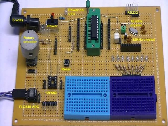
- Home Built PIC Development Board
- PIC16F628 PIC Using Rotary Encoder to Operate Stepper Motor
- Using a Serial ADC with PIC16F628
- Calculating Pulse-Width Modulation with a PIC
- PIC16F84A-628A Hardware Time Delays
- PIC16F84A-628A Timer Interrupt Delays
- PIC16F84A-628A Pullups and Interrupts
- PIC16F84A-628A Hardware Interrupts Tutorial
- Projects using PIC16F628:
- Home Built PIC16F628 Prototyping Board
- Exploring the Microchip PIC in Assembly
- Using a Microchip PIC with TLC548 Serial ADC
- Controlling PIC Pulse Width Modulation with a Serial ADC
- Using TMR0 on a PIC with Interrupts
- External Clock Crystal with PIC16F628 TMR1 Generates Interrupt
- PIC Using Rotary Encoder to Operate Stepper Motor
- PIC16F628 Pulse Width Modulation Controls Brightness of LED
- Another way to Turn On-Off PWM in a PIC
- TLC548 Serial ADC Spec. Sheet
- Programming PIC16F84A-PIC16F628A Interrupts by Example
- PIC16F84A-PIC16F628A Pull Up Resistors with Interrupts
- Programming PIC16F84A-PIC16f628a Timers by Example
- Programming PIC16F84A-PIC16F628A TMR0 Interrupts
- Programming PIC16F84A Software Delay Routines by Example
Web site Copyright Lewis Loflin, All rights reserved.
If using this material on another site, please provide a link back to my site.